Image pickup apparatus and image shake correction method

a technology of image pickup and image shake, which is applied in the direction of exposure control, printing, instruments, etc., can solve the problems of image quality tending to degrade and the larger the image shake, and achieve the effect of suppressing the degradation of image quality and expanding the correctable range of image shak

Active Publication Date: 2012-11-22
JVC KENWOOD CORP A CORP OF JAPAN
View PDF4 Cites 26 Cited by
  • Summary
  • Abstract
  • Description
  • Claims
  • Application Information

AI Technical Summary

Benefits of technology

[0019]According to the present invention, it is possible to extend the correctable range of an image shake while suppressing degradation in image quality.

Problems solved by technology

As described above, the image quality tends to degrade by the electronic shake correction compared to the optical shake correction.
Further, the higher the magnification of zoom, the larger the image shake becomes.

Method used


Image

  • Image pickup apparatus and image shake correction method
  • Image pickup apparatus and image shake correction method
  • Image pickup apparatus and image shake correction method

Examples


first embodiment

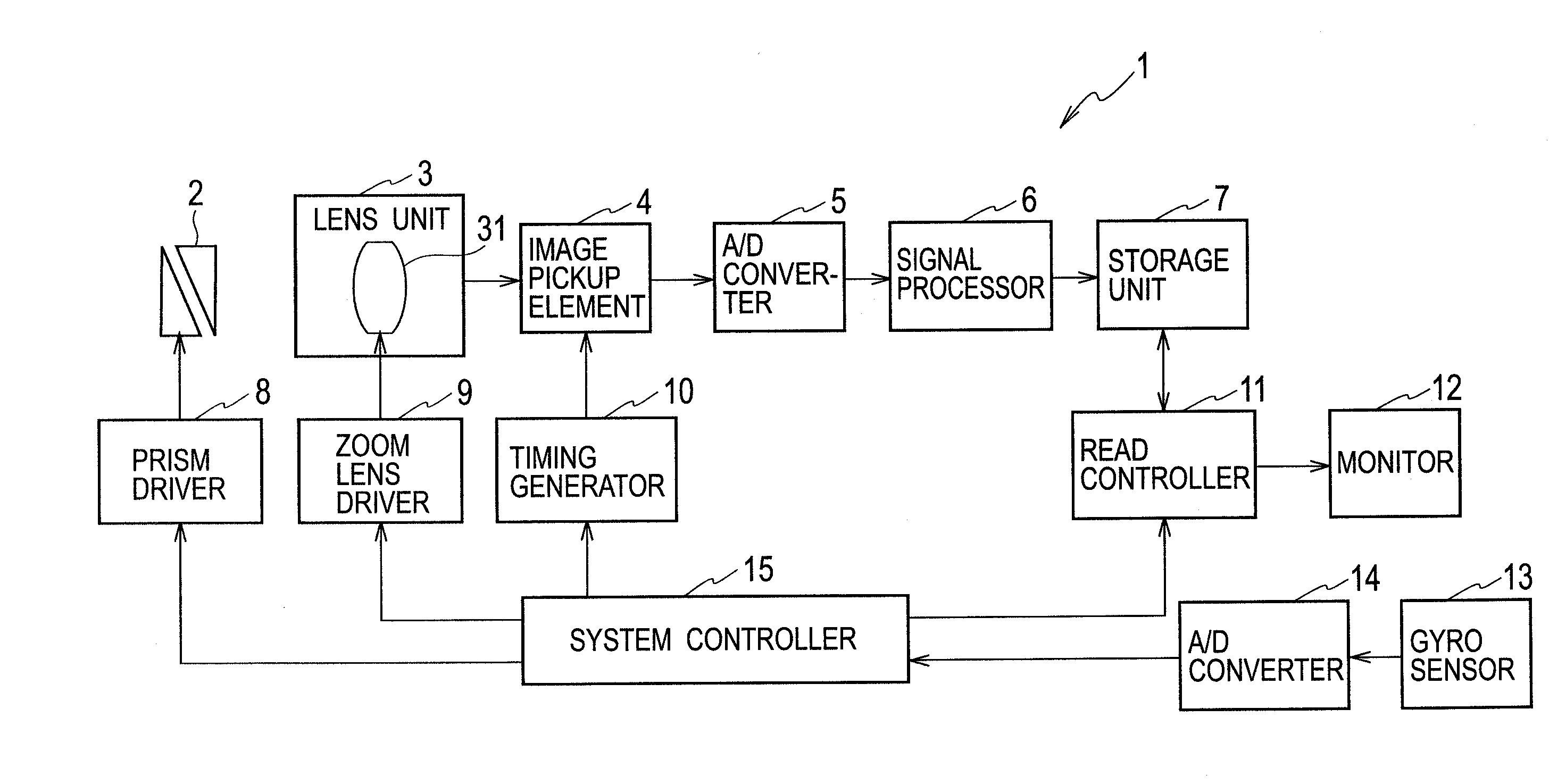
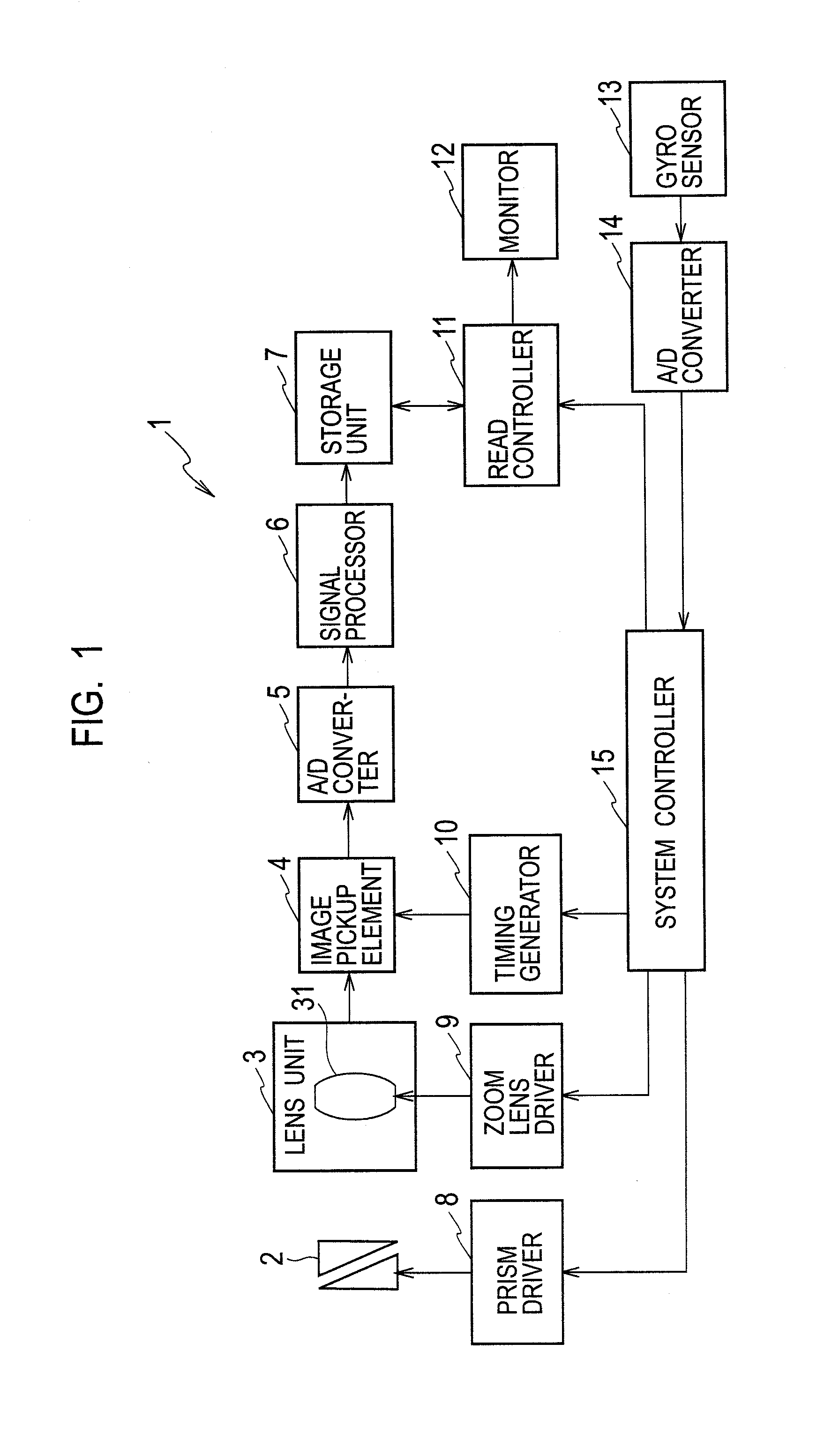
[0026]FIG. 1 is a block diagram showing a configuration of an image pickup apparatus according to a first embodiment of the present invention. As shown in FIG. 1, an image pickup apparatus 1 according to the first embodiment includes a prism 2, a lens unit 3, an image pickup element 4, an A / D converter 5, a signal processor 6, a storage unit 7, a prism driver 8, a zoom lens driver 9, a timing generator 10, a read controller 11, a monitor 12, a gyro sensor 13, an A / D converter 14, and a system controller 15.

[0027]The prism 2 is provided on the incidence side of light relative to the lens unit 3 and changes an optical axis angle of incident light from a subject to cause the light to enter the lens unit 3.

[0028]The lens unit 3 has a focusing lens group (not shown schematically) for performing focusing a zoom lens group 31 for optical zoom, etc., and forms an image of the incident light entering via the prism 2 on the image pickup element 4.

[0029]The image pickup element 4 includes a CC...

second embodiment

[0075]An image pickup apparatus according to a second embodiment has the same configuration as that of the image pickup apparatus 1 of the first embodiment, and therefore explanation is given using FIG. 1.

[0076]In the second embodiment, the system controller 15 sets the optical correction ratio R_ratio in accordance with the shutter speed (exposure time) of the electronic shutter in the image pickup element 4.

[0077]FIG. 5 is a diagram showing a relationship between the shutter speed and R_ratio in the second embodiment. As shown in FIG. 5, the higher the shutter speed (the shorter the exposure time), the lower R_ratio is set.

[0078]In addition, at the normal shutter speed (exposure time of 1 / 60 seconds), R_ratio=1 is set, that is, the correction is made by using only the optical shake correction.

[0079]On the other hand, at the highest shutter speed (for example, exposure time of 1 / 250 seconds), R_ratio is set so that the ratio between R_ratio and D_ratio and the ratio between Rmax an...


PUM


Abstract

A system controller sets an optical correction ratio, which is a distribution ratio in which a shake angle detected by a gyro sensor is distributed to optical shake correction, in accordance with an optical zoom magnification and controls a prism driver to correct the shake angle multiplied by the optical correction ratio by the optical shake correction, and also controls a read controller to correct the rest of the angle by electronic shake correction.

Description

TECHNICAL FIELD[0001]The present invention relates to an image pickup apparatus that picks up an image of a subject and an image shake correction method used by the same.BACKGROUND ART[0002]There have been known optical shake correction and electronic shake correction as a method for correcting an image shake resulting from a hand shake in image pickup apparatuses using image pickup elements, such as a CCD (Charge Coupled Device) and CMOS (Complementary Metal Oxide Semiconductor). The optical shake correction is a method for optically correcting a shake of a photographed image by changing the optical axis angle of light incident on the image pickup element and the electronic shake correction is a method for electronically correcting a shake of a photographed image by controlling a cut-out position of the photographed image stored in a memory.[0003]Both the optical shake correction and the electronic shake correction have a finite correctable range due to the configuration thereof. I...

Claims


Application Information

Patent Timeline
Patent Type & Authority Applications(United States)
IPC IPC(8): H04N5/228
CPCG03B5/00G03B2217/005H04N5/23248H04N5/23258G03B2207/005H04N5/23283H04N5/23296G03B2205/0046G03B2205/003H04N5/23267H04N23/68H04N23/6812H04N23/683H04N23/686H04N23/69H04N23/6842H04N23/6811G02B27/646
Inventor NONAKA, HIROTAKAKATOH, HIDEHIROKUBOTA, TEPPEI
Owner JVC KENWOOD CORP A CORP OF JAPAN
Why Eureka
Try Eureka