Variable z0 antenna device design system and method

a technology of antenna device and antenna frequency, applied in the direction of pulse technique, resonant antenna, instruments, etc., can solve the problems of limiting the work efficiency the rate or throughput of the associated device, and the speed of the antenna, so as to improve the vswr, improve the performance, and improve the maximum gain

Inactive Publication Date: 2012-12-27
MEGAWAVE CORP
View PDF34 Cites 25 Cited by
  • Summary
  • Abstract
  • Description
  • Claims
  • Application Information

AI Technical Summary

Problems solved by technology

In many cases antenna performance limits how well its associated device works.
Oftentimes the limitation is bandwidth-related, which may constrain data rates or throughput, thereby limiting, for example, how quickly an image might display or a web page takes to load.

Method used


Image

  • Variable z0 antenna device design system and method
  • Variable z0 antenna device design system and method
  • Variable z0 antenna device design system and method

Examples


Embodiment Construction

[0025]The invention is susceptible of many embodiments. What follows is illustrative, but not exhaustive, of the scope of the invention.

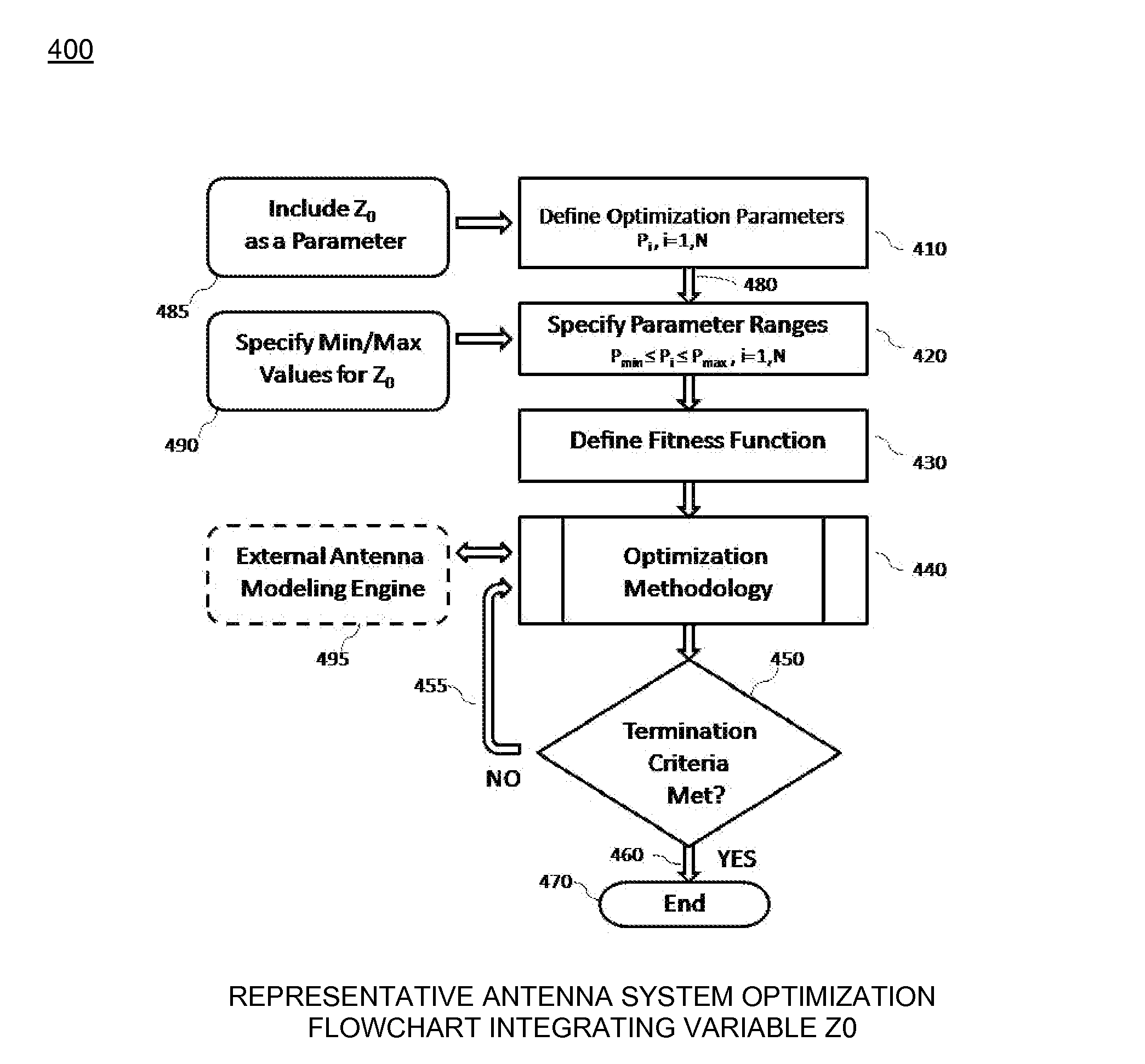
[0026]The Variable Z0 System and Method disclosed herein mitigates many antenna limitations by departing dramatically from the traditional approach to antenna system design or optimization (“D / O”). The Variable Z0 System and Method (“Variable Z0”) provides that the value of an antenna's feed system characteristic impedance or apparatus internal impedance (impedance of an antenna feed system), herein denoted Z0, be allowed to change as a true variable quantity during the antenna system design or optimization methodology and whose value be allowed to be determined by the methodology, because different values of Z0 result in different antenna system performance that often is considerably improved. Variable Z0 removes the limitation of specifying a value for Z0 in advance, and this invention yields unexpected benefits by doing so. The term “design” refe...


PUM


Abstract

A variable Z0 impedance method (“Variable Z0”) for designing and / or optimizing antenna systems. The method provides that the value of an antenna's feed system characteristic impedance or apparatus internal impedance (Z0) changes as a true variable quantity during the antenna system design or optimization methodology. The value is allowed to be determined by the methodology, because different values of Z0 result in different antenna system performance. It is applied to any set of performance objectives on any antenna system wherein apparatus internal or transmission line characteristic impedance is an explicit or implicit parameter. Variable Z0 is applied to any design or optimization methodology. Structures include Yagi-Uda arrays, Meander Monopoles, and transmission line Multi-Stub Matching Networks, and can incorporate Central Force Optimization or Biogeography Based Optimization or other optimization algorithms.

Description

RELATED APPLICATION[0001]This application claims the benefit of U.S. Provisional Application No. 61 / 531,237 filed Sep. 6, 2011, incorporated herein by reference in its entirety for all purposes.COPYRIGHT NOTICE[0002]A portion of the disclosure of this patent document contains material that is subject to copyright protection. The copyright owner has no objection to the facsimile reproduction by anyone of the patent document or the patent disclosure, as it appears in a published Patent and Trademark Office patent file or record, but otherwise reserves all copyrights whatsoever.FIELD OF THE INVENTION[0003]The invention relates to a system and method for creating antenna devices by providing parameters of their fabrication.BACKGROUND OF THE INVENTION[0004]Antennas, the devices that emit (radiate) and receive electromagnetic radiation, have become progressively more important in the modern world. Even though many, if not most, antennas today are “invisible,” literally out-of-sight becaus...

Claims


Application Information

Patent Timeline
Patent Type & Authority Applications(United States)
IPC IPC(8): G06F17/50
CPCH01Q1/36H01Q1/50H04B7/185H04B7/14H03K17/92H01Q1/00H01L35/00Y10S439/916G06F17/5081G06F17/5072G06F17/5004G06F17/15G06F17/11H01L29/12G06F17/5068H01Q9/42G06F30/39G06F30/392G06F30/13G06F30/398H10N10/00
Inventor FORMATO, RICHARD A.
Owner MEGAWAVE CORP
Why Eureka
Try Eureka