Capacitance unit and stacked solid electrolytic capacitor

Active Publication Date: 2013-01-10
APAQ TECH
View PDF7 Cites 8 Cited by
  • Summary
  • Abstract
  • Description
  • Claims
  • Application Information

AI Technical Summary

Benefits of technology

[0011]The colloid portion, in the exemplary embodiments, covers a partial surface of the cathode portion so that the thickness of the manufactured capacitance unit is uniform. As a result, the packaging unit has improved packaging strengt

Problems solved by technology

Further, the thin wall thickness of the packaging material causes the low mechanical strength of the packaging material so that the inner material may be exposed easily, or the airtightness of the packaging material may be decreased.
In other words,

Method used


Image

  • Capacitance unit and stacked solid electrolytic capacitor
  • Capacitance unit and stacked solid electrolytic capacitor
  • Capacitance unit and stacked solid electrolytic capacitor

Examples


Example

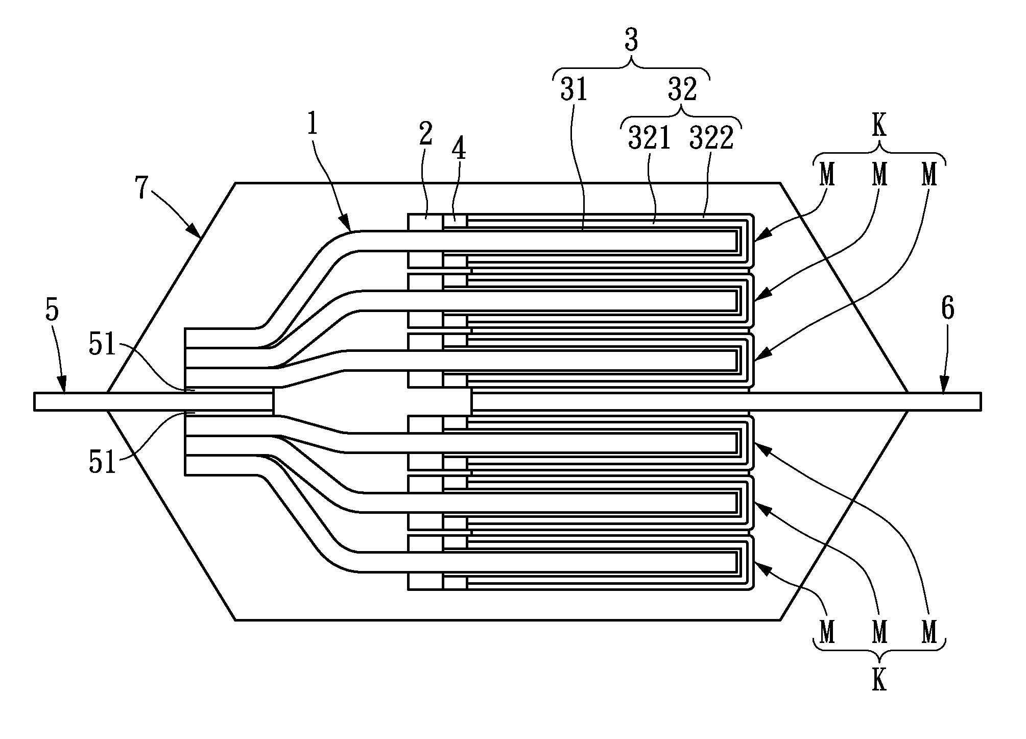
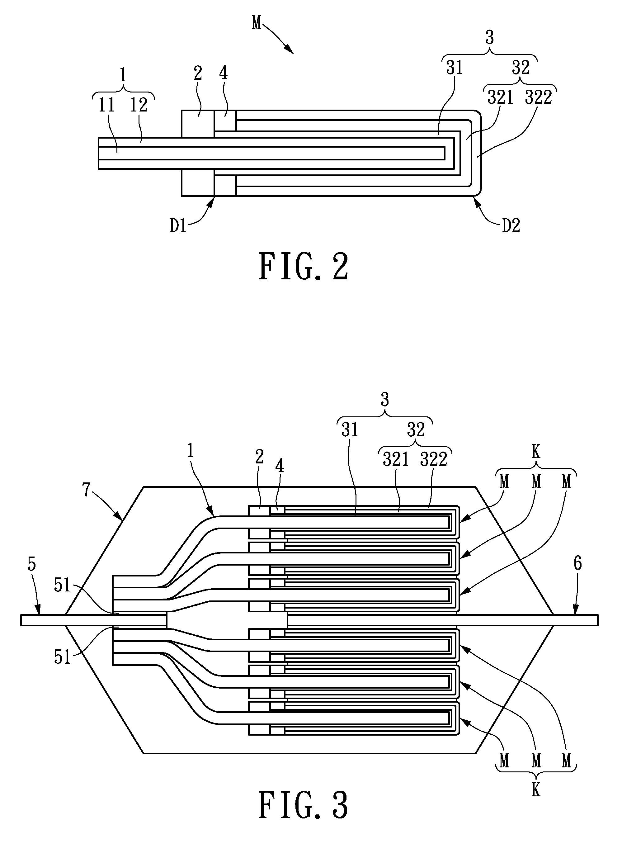
[0019]Please refer to FIGS. 2 and 3; the instant disclosure provides the first embodiment of the stacked solid electrolytic capacitor which includes two capacitor modules K, an anode conduction unit 5, a cathode conduction unit 6 and a packaging unit 7.

[0020]Each of the two capacitor modules K has a plurality of capacitance units M and each of the capacitance units M has an anode portion 1, a cathode portion 3, an insulating portion 2 and a colloid portion 4.

[0021]In detail, the anode portion 1 is constructed by an aluminum foil 11 and a dielectric layer 12 of aluminum oxide covered on the aluminum foil 11. The anode portion 1 is insulated from the cathode portion 3 by the dielectric layer 12.

[0022]Furthermore, the insulating portion 2 surrounds the anode portion 1 and covers a first partial surface of the anode portion 1. Similar with the dielectric layer 12, the insulating portion 2 provides the insulation function between the anode portion 1 and the cathode portion 3.

[0023]The ca...

Example

[0040]The second exemplary embodiment is shown below.

[0041]As shown in FIG. 4, the second exemplary embodiment provides a stacked solid electrolytic capacitor which includes a capacitor unit K, an anode conduction unit 5, a cathode conduction unit 6 and a packaging unit 7. The capacitor module K has a plurality of capacitance units M and each of the capacitance units M has an anode portion 1, a cathode portion 3, an insulating portion 2 and a colloid portion 4. An anode terminal may be formed on the front end of the anode portion 1. The insulating portion 2 surrounds the anode portion 1 and covers a first partial surface of the anode portion 1, and the cathode portion 3 is disposed next to the insulating portion 2 and covers a second partial surface of the anode portion 1. The colloid portion 4 is disposed next to the insulating portion 2. The colloid portion 4 surrounds the cathode portion 3 and covers a partial surface of the cathode portion 3.

[0042]The anode conduction unit 5 has...

Example

[0043]In structural difference between the first and the second embodiment, the capacitor unit K is only arranged on one side of the anode and cathode conduction units 5, 6. By arranging the capacitor unit K and the capacitance units M, the size and the capacity of the final product may be flexibly adjusted.

[0044]The present invention at least has the following characteristics. The thickness of the final capacitor is uniform because the colloid portion covers a partial surface of the cathode portion. Accordingly, the packaging strength may be improved and the inner materials are completely covered and protected. The colloid portion has high airtightness for keeping the capacitor materials from moisture so that the electrical property is stable and the current-leakage is avoided.

[0045]The description above only illustrates specific embodiments and examples of the present invention. The present invention should therefore cover various modifications and variations made to the herein-de...


PUM


Abstract

A capacitance unit includes an anode portion, an insulating portion, a cathode portion and a colloid portion. The front end of the anode portion extends to from an anode terminal. The insulating portion surrounds the anode portion and covers a first partial surface of the anode portion. The cathode portion is disposed next to the insulating portion, and the cathode portion covers a second partial surface of the anode portion. The colloid portion is disposed next to the insulating portion, and the colloid portion surrounds the cathode portion and covers a partial surface of the cathode portion.

Description

BACKGROUND OF THE INVENTION[0001]1. Field of the Invention[0002]The present invention relates to a capacitance unit and a stacked solid electrolytic capacitor. In particular, the present invention relates to a capacitance unit and a stacked solid electrolytic capacitor having uniform thickness.[0003]2. Description of Related Art[0004]Capacitors are widely used in modern electronic products for storing electrical charge, filtering, bypassing or tune-oscillating. Because of the different capacitor properties, capacitors in different types are chosen in different applications. Solid electrolytic capacitors have properties of high capacity, a small size, high-frequency characteristics and low manufacturing cost; therefore, the solid electrolytic capacitors are more and more used in various applications, such as electric devices and electronic products.[0005]Please refer to FIGS. 1A and 1B; the traditional capacitors are shown. Due to the structure and the manufacturing processes in the ...

Claims


Application Information

Patent Timeline
IPC IPC(8): H01G9/15H01G9/028H01G9/00
CPCH01G9/15H01G9/14H01G9/10H01G9/012
Inventor CHIU, CHI-HAOLIN, CHING-FENGCHANG, KUN-HUANG
Owner APAQ TECH
Why Eureka
Try Eureka