Relaxation oscillator circuit including two clock generator subcircuits having same configuration operating alternately

a technology of oscillator circuit and clock generator, which is applied in the direction of pulse generation by vacuum tubes, pulse manipulation, pulse technique, etc., can solve the problems of frequency fluctuation, inability to suppress the fluctuations in clock frequency caused by output fluctuations

Inactive Publication Date: 2013-02-28
SEMICON TECH ACADEMIC RES CENT
View PDF2 Cites 5 Cited by
  • Summary
  • Abstract
  • Description
  • Claims
  • Application Information

AI Technical Summary

Benefits of technology

[0018]According to the relaxation oscillator circuit of the present invention, for the comparison voltage generating interval, the control circuit holds the second output voltage when the level of the output signal from the comparator is inverted as the comparison voltage of the comparator. For the clock generating interval, the control circuit charges the first capacitor with the first constant current until the level of the output signal from the comparator is inverted. In addition, the control circuit controls the first and second clock generator subcircuits, so that one subcircuit of the first and second clock generator subcircuits operates for the comparison voltage generating interval, then another subcircuit operates for the clock generating interval, and so that the first and second clock generator subcircuits alternately repeat processes of the comparison voltage generating interval and the clock generating interval. The control circuit generates a clock based on output signals from the comparators of the first and second clock generator subcircuits. Therefore, according to the relaxation oscillator circuit of the present invention, it is possible to generate a clock having a frequency more constant than that of the prior art.

Problems solved by technology

However, the relaxation oscillator circuit has such a problem that a frequency (referred to as a clock frequency hereinafter) of a clock to be outputted therefrom fluctuates due to variations in the manufacturing processes of comparators for comparing a voltage across both terminals of the capacitor with a predetermined reference voltage.
However, according to the Non-Patent Document 1, it was not possible to suppress the fluctuations in the clock frequency caused by the delay of the comparator.
In addition, according to the Non-Patent Document 2, there is such a problem that the clock frequency fluctuates due to the offset voltage of an op-amp used in the integrator circuit since the integrator circuit is newly employed.
Further, because it is required to use a resistor having a relatively high resistance value in the integrator circuit, the circuit area could not be reduced.

Method used


Image

  • Relaxation oscillator circuit including two clock generator subcircuits having same configuration operating alternately
  • Relaxation oscillator circuit including two clock generator subcircuits having same configuration operating alternately
  • Relaxation oscillator circuit including two clock generator subcircuits having same configuration operating alternately

Examples


first preferred embodiment

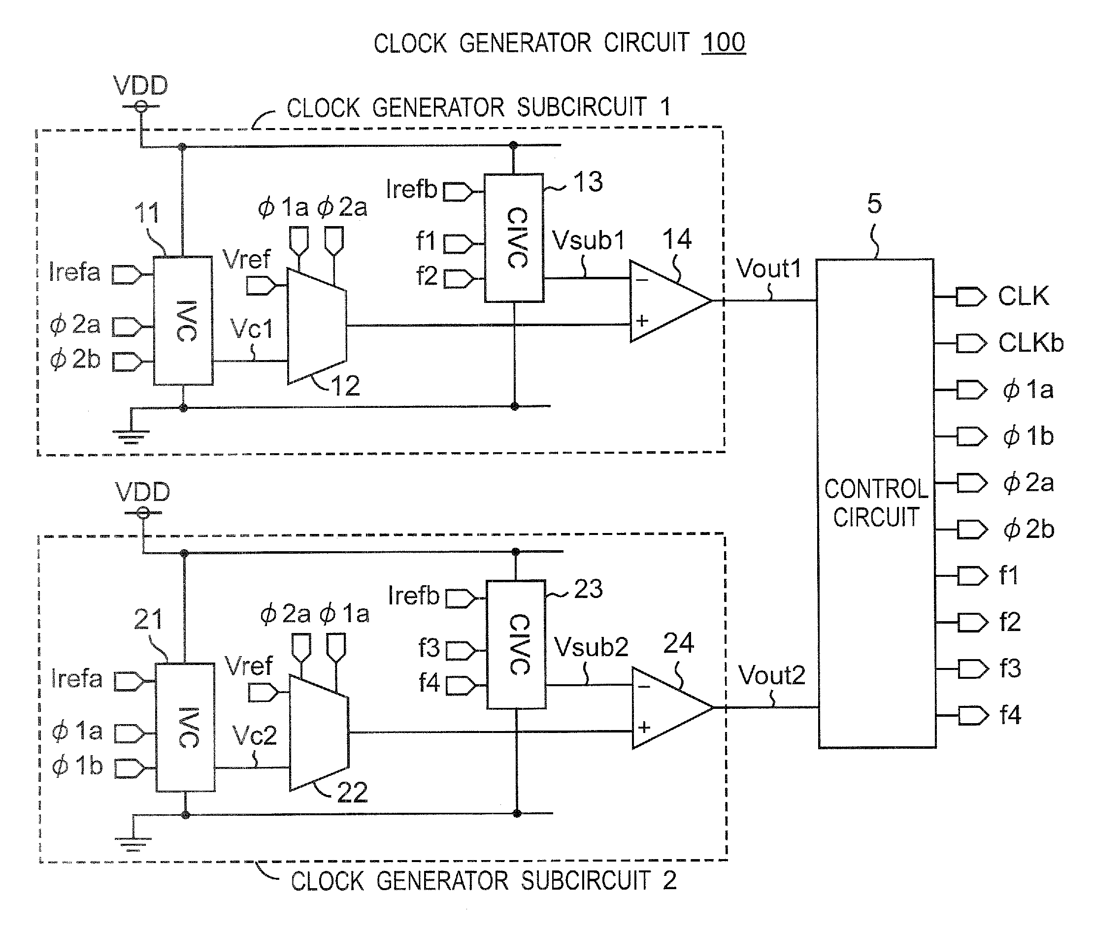
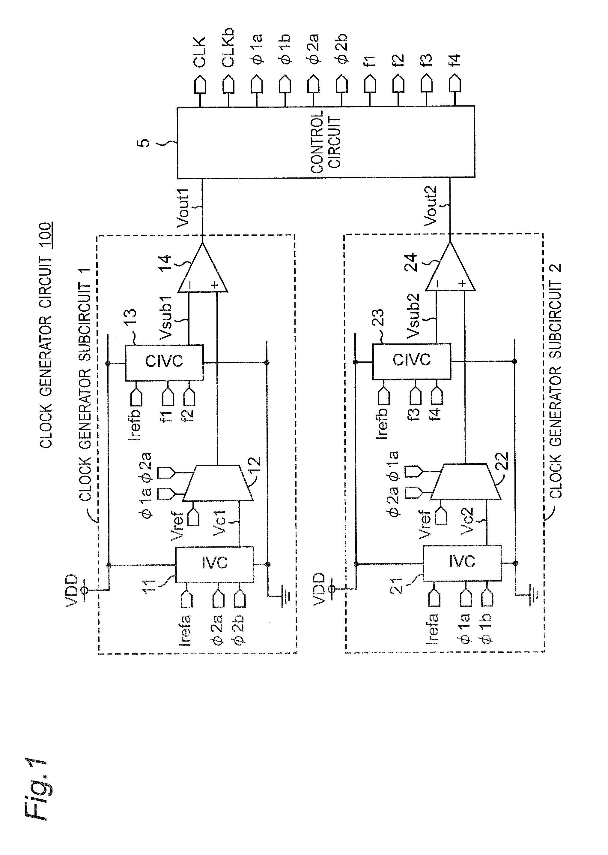
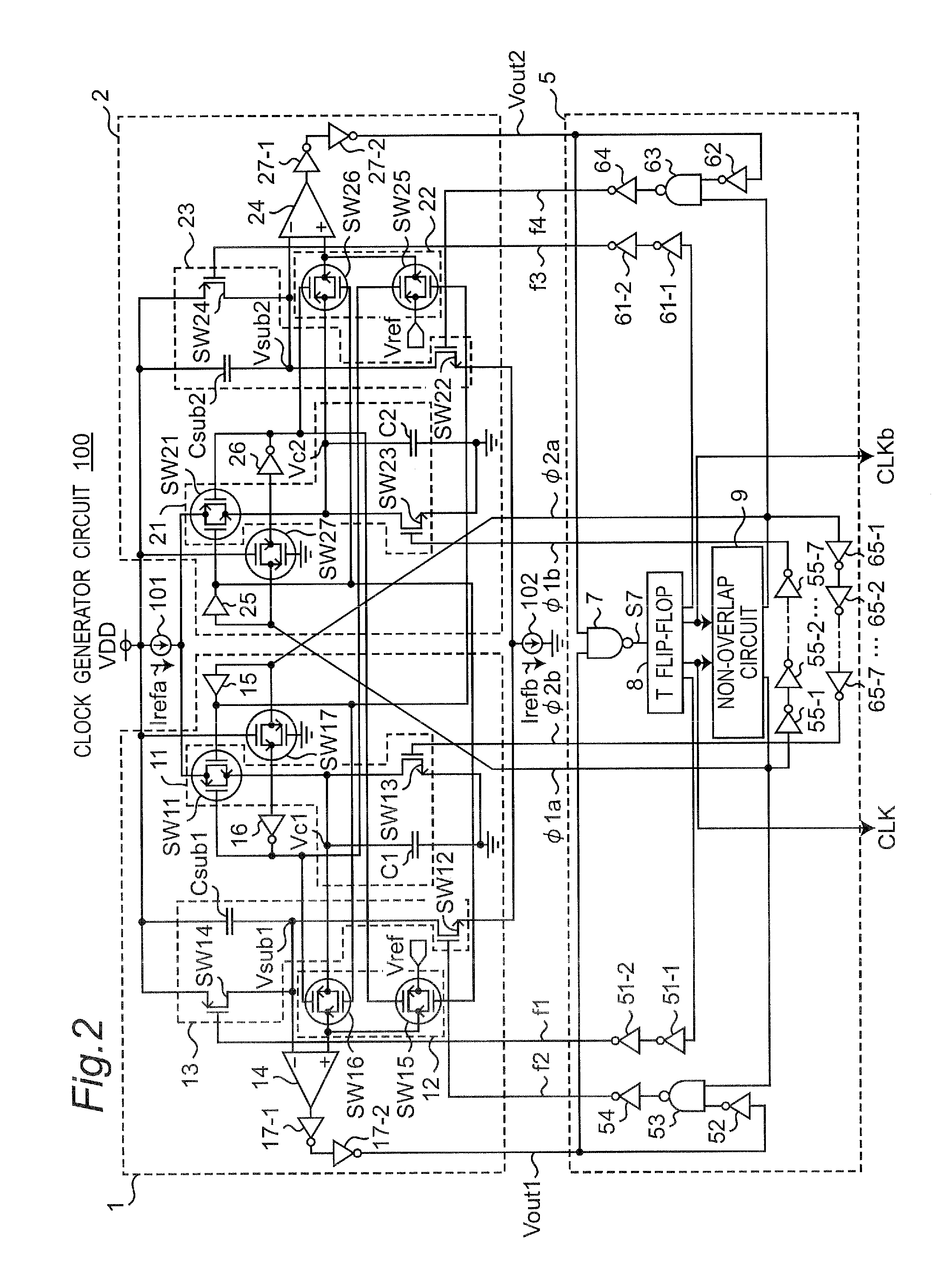
[0045]FIG. 1 is a block diagram showing a configuration of a clock generator circuit 100 according to the first preferred embodiment of the present invention, and FIG. 2 is a circuit diagram showing a configuration of the clock generator circuit 100 of FIG. 1. In addition, FIG. 3 is a circuit diagram showing a configuration of a T flip-flop 8 of FIG. 2, and FIG. 4 is a circuit diagram showing a configuration of a non-overlap circuit 9 of FIG. 2.

[0046]Referring to FIG. 1, the clock generator circuit 100 is a relaxation oscillator circuit, and is configured to include clock generator subcircuits 1 and 2, and a control circuit 5. In addition, the clock generator subcircuit 1 is configured to include a current-voltage converter circuit (I-V converter (IVC)) 11, a multiplexer 12, a complementary current-voltage converter circuit (complementary I-V converter (CIVC)) 13, and a comparator 14. The complementary current-voltage converter circuit 13 has a configuration complementary to that of...

second preferred embodiment

[0092]FIG. 12 is a circuit diagram showing a configuration of a clock generator circuit 100A according to the second preferred embodiment of the present invention. The clock generator circuit 100A of FIG. 12 is different from the clock generator circuit 100 of FIG. 2 in the point that current generator subcircuits 1A and 2A are provided instead of the current generator subcircuits 1 and 2, respectively.

[0093]In the first preferred embodiment (See FIG. 2), the switch SW14 of the current generator subcircuit 1 is connected in parallel with the capacitor Csub1, which has the first electrode grounded via the switch SW12 and the second electrode connected to the power source VDD. In contrast to this, a current source 105 that outputs a predetermined constant current Irefd is connected between the switch SW14 and the power source VDD in the current generator subcircuit 1A of FIG. 12. Namely, the switch SW14 is connected in parallel with the capacitor Csub1 via the current source 105. The ...


PUM


Abstract

A control circuit controls first and second clock generator subcircuits so that one subcircuit of the first and second clock generator subcircuits operates for a comparison voltage generating interval, then another subcircuit operates for a clock generating interval, and so that the first and second clock generator subcircuits alternately repeat processes of the comparison voltage generating interval and the clock generating interval. For the comparison voltage generating interval, each of the first and second clock generator subcircuits is controlled to generate a comparison voltage and output the same voltage to an inverted output terminal of a comparator. For the clock generating interval, each of the first and second clock generator subcircuits compares an output voltage from a current-voltage converter circuit with the comparison voltage.

Description

BACKGROUND OF THE INVENTION[0001]1. Field of the Invention[0002]The present invention relates to a relaxation oscillator circuit for generating a clock. In particular, the present invention relates to a relaxation oscillator circuit including two clock generator subcircuit.[0003]2. Description of the Related Art[0004]In recent years, due to the development of a number of micro systems such as implanted devices for use in medical applications and sensor devices, Large Scale Integrations (LSIs) are required to operate with a ultralow power. Therefore, a clock generator circuit to be mounted on an LSI is also required to operate with a low power, and is required to be on-chip mounted. A relaxation oscillator circuit is employed as a clock generator circuit that satisfies the above-described requirements. The relaxation oscillator circuit executes oscillating operation (referred to as a relaxation oscillating operation hereinafter) by charging and discharging a capacitor. However, the r...

Claims


Application Information

Patent Timeline
Patent Type & Authority Applications(United States)
IPC IPC(8): H03K3/02
CPCH03K3/011H03K5/1515H03K3/354
Inventor SHIGA, SEICHIROHIROSE, TETSUYAOSAKI, YUJI
Owner SEMICON TECH ACADEMIC RES CENT
Why Eureka
Try Eureka