Ultrasonic wave detection apparatus, recording material determination apparatus, and image forming apparatus

a technology of ultrasonic wave detection and recording material, which is applied in the direction of instruments, electrographic processes, magnetic properties, etc., can solve the problems of defective image generation and inability to optimize image forming conditions, and achieve the effect of accurately obtaining the detection timing of a target ultrasonic wav

Inactive Publication Date: 2013-02-28
CANON KK
View PDF3 Cites 7 Cited by
  • Summary
  • Abstract
  • Description
  • Claims
  • Application Information

AI Technical Summary

Benefits of technology

[0008]Exemplary embodiments of the present invention are directed to a technique capable of accurately obtaining detection timing of a target ultrasonic wave without performing any correction operation considering environmental factors.

Problems solved by technology

However, if a user forgets or fails in setting a type of a recording material, it is unable to optimize image forming conditions.
A defective image may be generated.

Method used


Image

  • Ultrasonic wave detection apparatus, recording material determination apparatus, and image forming apparatus
  • Ultrasonic wave detection apparatus, recording material determination apparatus, and image forming apparatus
  • Ultrasonic wave detection apparatus, recording material determination apparatus, and image forming apparatus

Examples


Embodiment Construction

[0036]Various exemplary embodiments, features, and aspects of the invention will be described in detail below with reference to the drawings.

[0037]Constituent components described in the following exemplary embodiments can be appropriately modified in their dimensions, materials, shapes, and relative layout considering the configuration and various conditions of an apparatus to which the present invention is applied. Accordingly, the scope of the present invention is not limited to the following exemplary embodiments unless it is specially mentioned.

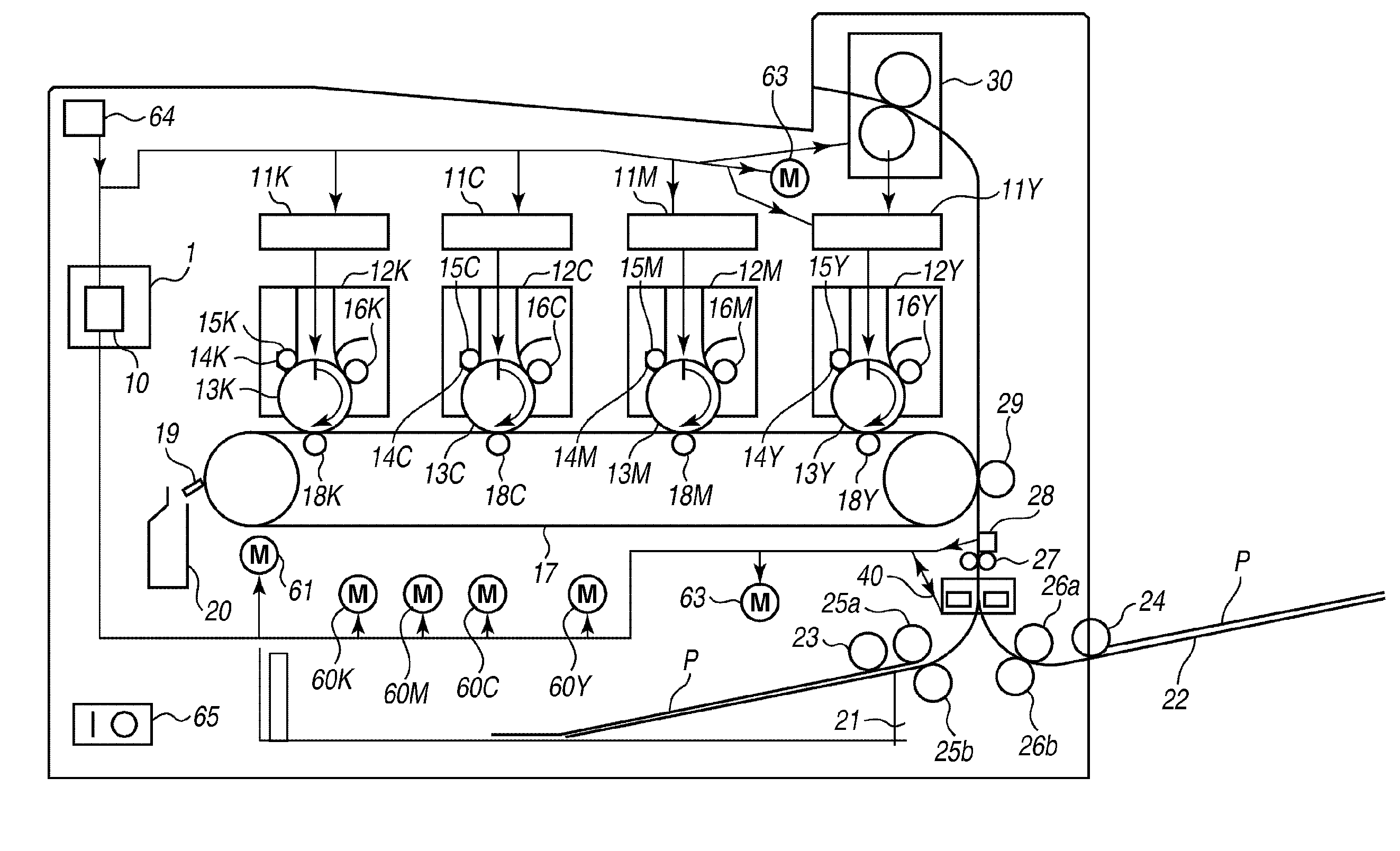
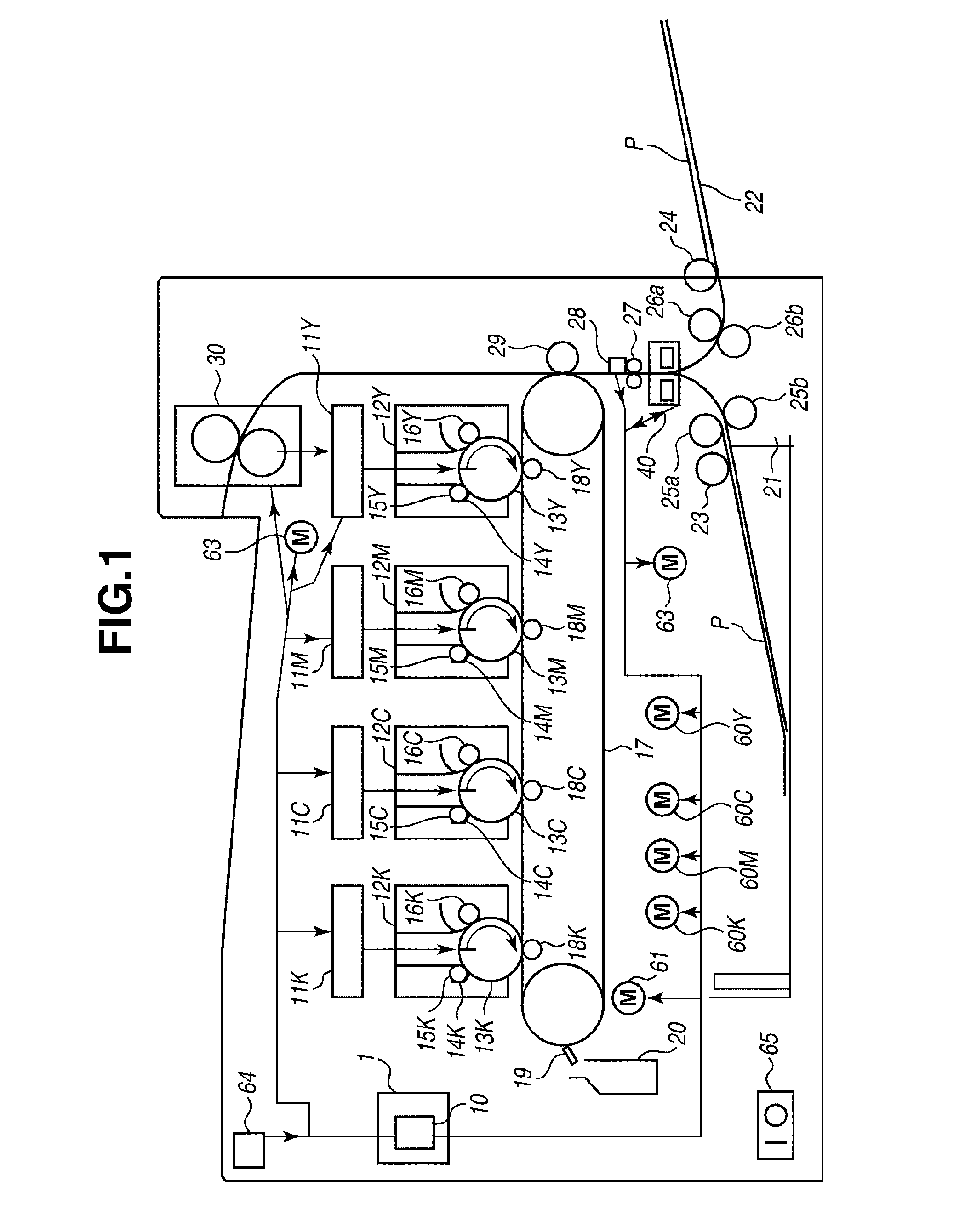
[0038]An ultrasonic wave detection apparatus according to a first exemplary embodiment is, for example, usable for an image forming apparatus, such as a copy machine and a printer. FIG. 1 schematically illustrates an example configuration of an inline type color image forming apparatus as an example of the ultrasonic wave detection apparatus. The image forming apparatus includes the following configuration.

[0039]The inline type color ima...


PUM

PropertyMeasurementUnit
frequencyaaaaaaaaaa
frequencyaaaaaaaaaa
frequencyaaaaaaaaaa

Abstract

An ultrasonic wave detection apparatus includes a transmission unit which transmits ultrasonic waves at a first frequency and a second frequency, a reception unit which receives ultrasonic waves transmitted from the transmission unit, and a control unit which causes the transmission unit to transmit ultrasonic waves at the first frequency and causes the reception unit to receive the first frequency ultrasonic waves to obtain a detection timing of a peak value of a n-th wave of the received first frequency ultrasonic waves, causes the transmission unit to transmit ultrasonic waves at the second frequency and causes the reception unit to receive the second frequency ultrasonic waves to obtain a detection timing of a peak value of a n-th wave of the received second frequency ultrasonic waves, and specifies “n” of the n-th wave from which the peak value is detected based on a difference in the detection timings.

Description

BACKGROUND OF THE INVENTION[0001]1. Field of the Invention[0002]The present invention relates to an apparatus for detecting a characteristic of a recording material using an ultrasonic wave.[0003]2. Description of the Related Art[0004]A conventional image forming apparatus enables a user to set a type of a recording material (which may be referred to as “paper type”) via an operation panel provided on as an external apparatus, such as a computer, or on the body of the image forming apparatus. The image forming apparatus can be controlled in such a way as to optimize image transfer conditions (e.g., bias, an image forming speed) and image fixing conditions (e.g., a quantity of heat, a recording material conveyance speed) according to the settings.[0005]However, if a user forgets or fails in setting a type of a recording material, it is unable to optimize image forming conditions. A defective image may be generated. Therefore, to reduce a burden on a user or to appropriately control t...

Claims


Application Information

Patent Timeline
Patent Type & Authority Applications(United States)
IPC IPC(8): G03G15/00G01N29/04
CPCG01N29/348G01N29/38G03G2215/00738G03G2215/00637G03G15/65B65H2553/30B65H2557/64
Inventor MORI, ATSUNOBU
Owner CANON KK
Why Eureka
Try Eureka