
GIS partial discharge detection method and device, medium and terminal equipment

A partial discharge detection and local technology, applied in the direction of testing dielectric strength, etc., can solve the problems of neglecting discharge defects, high accuracy requirements of time-of-arrival verification instruments, etc., to achieve the effect of improving accuracy and accurate detection time

Active Publication Date: 2022-04-15
GUANGDONG POWER GRID CO LTD +1
View PDF9 Cites 0 Cited by
  • Summary
  • Abstract
  • Description
  • Claims
  • Application Information

AI Technical Summary

Problems solved by technology

[0003] However, the existing partial discharge location technology usually only collects a small amount of discharge pulses to locate the discharge source. When the distance between the partial discharge sensors is 1m, the time difference is below 5ns, so the accuracy of the arrival time verification instrument High accuracy requirements, and may need to take complex error correction measures to improve positioning accuracy
Moreover, this type of partial discharge localization can only be used for offline detection
In addition, when there are multiple discharge defects, the discharge signal with small pulse amplitude and low discharge frequency is easily covered by the discharge signal with large pulse amplitude and high discharge frequency, which may only focus on the discharge pulse of a certain defect during positioning, thus Other discharge defects are ignored

Method used

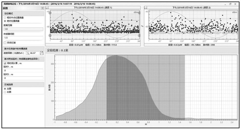
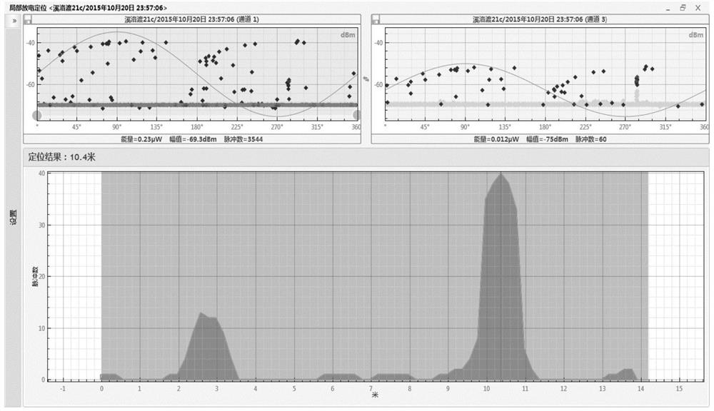

Image

  • GIS partial discharge detection method and device, medium and terminal equipment
  • GIS partial discharge detection method and device, medium and terminal equipment
  • GIS partial discharge detection method and device, medium and terminal equipment

Examples


Embodiment Construction

[0040] The following will clearly and completely describe the technical solutions in the embodiments of the present invention with reference to the accompanying drawings in the embodiments of the present invention. Obviously, the described embodiments are only some, not all, embodiments of the present invention. Based on the embodiments of the present invention, all other embodiments obtained by persons of ordinary skill in the art without creative efforts fall within the protection scope of the present invention.

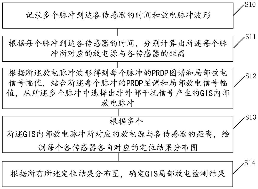
[0041] See figure 1 , an embodiment of the present invention provides a GIS partial discharge detection method, the method comprising:

[0042] S10. Obtain the time when multiple pulses arrive at each sensor and the waveform of the discharge pulse.

[0043] S11. Calculate the distance between the discharge source corresponding to each pulse and each sensor according to the time when each pulse arrives at each sensor.

[0044] S12. Obtain the PRPD spectrum and par...


PUM


Abstract

The invention discloses a GIS partial discharge detection method, a GIS partial discharge detection device, a medium and terminal equipment. The method comprises the following steps: acquiring the time when a plurality of pulses arrive at each sensor and a discharge pulse waveform; respectively calculating the distance between the discharge source corresponding to each pulse and each sensor according to the time when each pulse reaches each sensor; selecting a plurality of GIS internal discharge pulses generated by non-external interference signals from the plurality of pulses by combining the PRPD atlas of each pulse obtained from the discharge pulse waveform and the partial discharge signal amplitude; and drawing a positioning result distribution diagram corresponding to each sensor according to the distance between a discharge source corresponding to the plurality of GIS internal discharge pulses and each sensor, and determining a GIS partial discharge detection result according to the positioning result distribution diagram. By adopting the embodiment of the GIS partial discharge detection method provided by the invention, a plurality of pulses can be positioned at the same time and different types of pulses can be identified.

Description

technical field [0001] The invention relates to the field of GIS discharge detection, in particular to a GIS partial discharge detection method, device, medium and terminal equipment. Background technique [0002] The existing partial discharge location technology is mainly offline location, using the time difference method to carry out UHF signal location, collecting partial discharge pulse signals through multiple UHF sensors or ultrasonic sensors, and then obtaining the time when the discharge pulse reaches each sensor, and calculating these The position of the discharge source is obtained by combining the time difference of the moment with the sensor distance information. [0003] However, the existing partial discharge location technology usually only collects a small amount of discharge pulses to locate the discharge source. When the distance between the partial discharge sensors is 1m, the time difference is below 5ns, so the accuracy of the arrival time verification ...

Claims


Application Information

Patent Timeline
IPC IPC(8): G01R31/12
Inventor 王磊罗颖婷饶章权许海林刘建明魏瑞增孙晓敏邓梓颖王彤
Owner GUANGDONG POWER GRID CO LTD
Learn More