

DC Switching Device
- Summary
- Abstract
- Description
- Claims
- Application Information
AI Technical Summary
Benefits of technology
Problems solved by technology
Method used
Image

Examples
Embodiment Construction
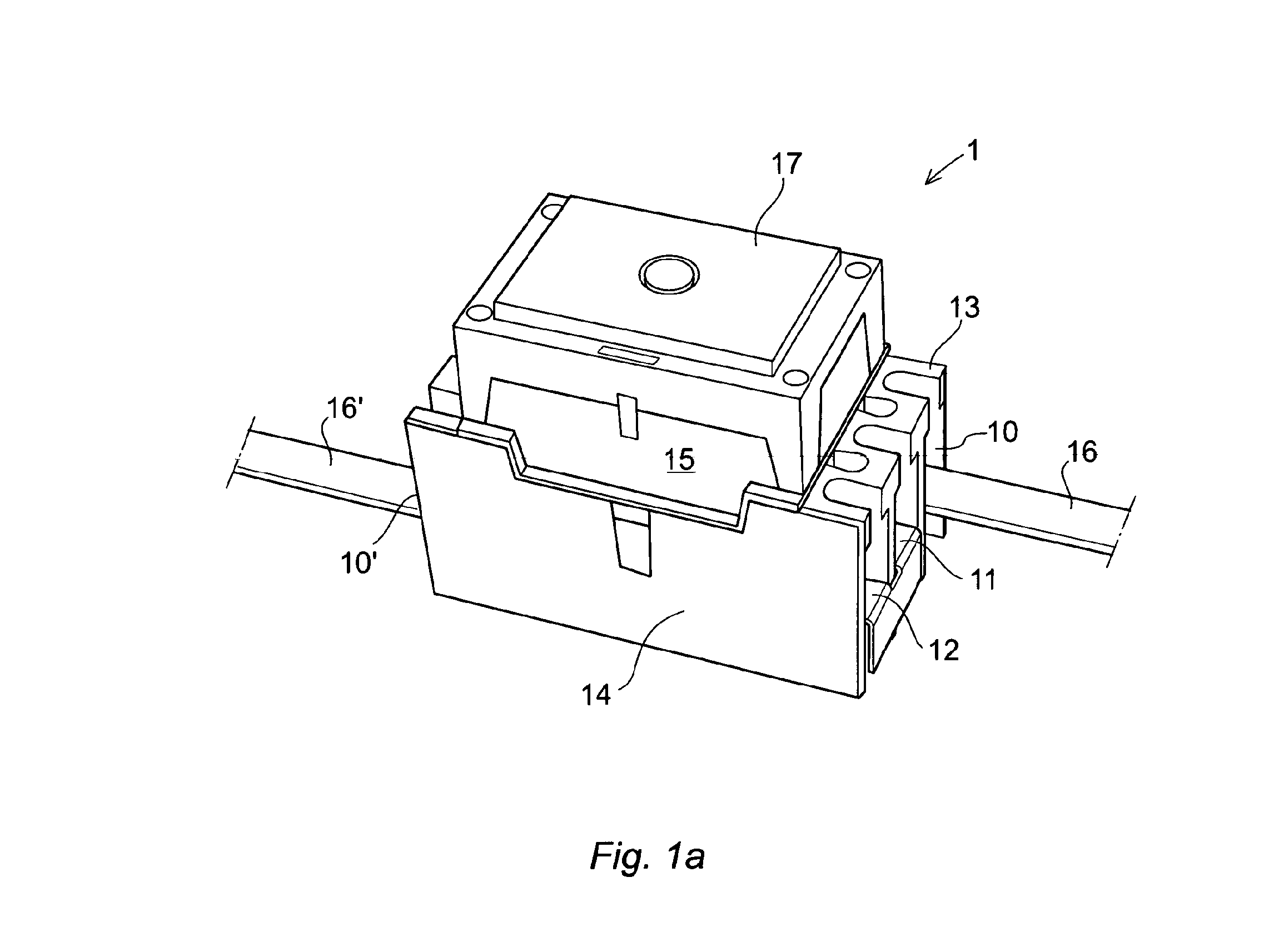
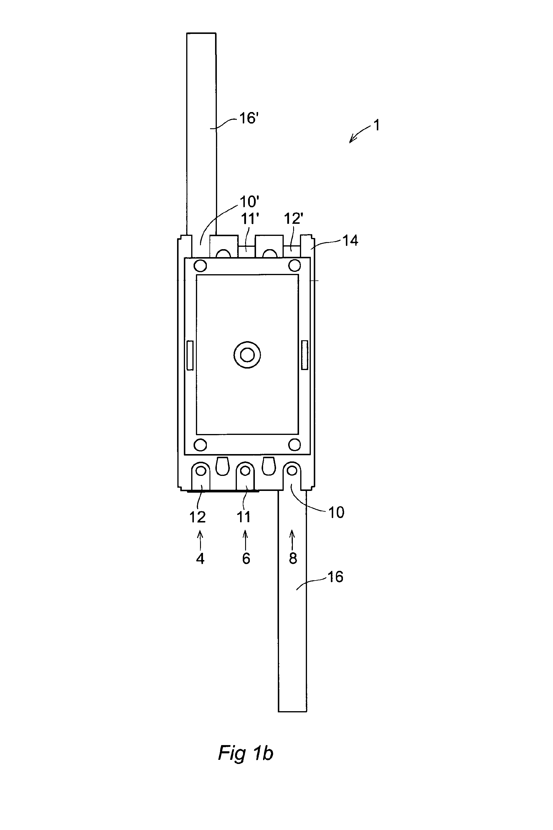
[0027]FIGS. 1a and 1b show respectively an isometric and an overhead view of a sealed electromagnetic contactor 1 comprising a housing portion 13 and a casing portion 17. The housing 13 is positioned at the bottom of the contactor in view of the FIG. 1a and includes further a frame 15 and a seat 14, while the casing portion 17 is positioned on the top part of the contactor. In this example, the contactor further includes six connectors 10, 11, 12, 10′, 11′ and 12′, wherein two connectors 10 and 10′ are arranged for connecting the contactor in an electric circuit via power terminals 16 and 16′ and, the connector 10 is connected to the terminals 16 adapted as an input terminal and the connector 10′ connected to the terminal 16′ adapted as an output terminal. While other four connectors 11, 11′, 12 and 12′ are connected in pair, meaning that the connectors 11 and 11′ are connected in series so do the connectors 12 and 12′. Therefore, all the connectors are connected in series for conne...
PUM
 Abstract
Description
Claims
Application Information