Garment MRI Antenna Array

Inactive Publication Date: 2013-05-30
SCANMED
View PDF3 Cites 53 Cited by
  • Summary
  • Abstract
  • Description
  • Claims
  • Application Information

AI Technical Summary

Benefits of technology

[0040]The present invention preferably optimizes coil size, configuration, the number of coil elements or resonators, and the positioning of those resonators about the subject via their being mounted on a flexible substrate, in order to achieve the desired performance, both in terms of S/N ratio, coverage and homogeneity. Further, the resonators are isolated from one another to such a degree so as not to interfere with one another's tuning and performance, and are preferably housed in a water-proof container that facilitates close fitting to the desired patient anatomy via draping the coil over, around or embedding the array within a pull-on garment. Further, these arrays will withstand high degrees of flexing in three dimensions and also withstand the weight of the patient distributed over the surface of the coil housing. Isolation amongst elements is achieved via a combination of two or more mechanisms: 1) geometric isolation between

Problems solved by technology

While the smaller local coil's size works to an advantage in obtaining a higher S/N ratio, this reduced size also presents a disadvantage for imaging deep-seated tissues.
Limitations exists with the aforementioned configuration of quadrature coils; that being that they are not laid out to provide optimal volumetric coverage—that is sensitivity from more than one side of the patient.
These configurations are limited as well due to that simple fact that each element of the quadrature pair has substantially different sensitivity (flux) profiles throughout the medial volume due to their positions being on opposite sides of the volume.
So, although the aforementioned patents describe volume coil arrays that provide more homogeneous signal quality throughout a volume, they do not yield the SNR performance locally to the quadrature coil sets described in the '378 patent.
This design is limited in the number of elements, has limited flexibility from a generally planar configuration, and doesn't address optimization of multiple elements on such a flexible form.
For proper tuning to be maintained, the relative flexible antenna structures must maintain thei

Method used


Image

  • Garment MRI Antenna Array
  • Garment MRI Antenna Array
  • Garment MRI Antenna Array

Examples


Embodiment Construction

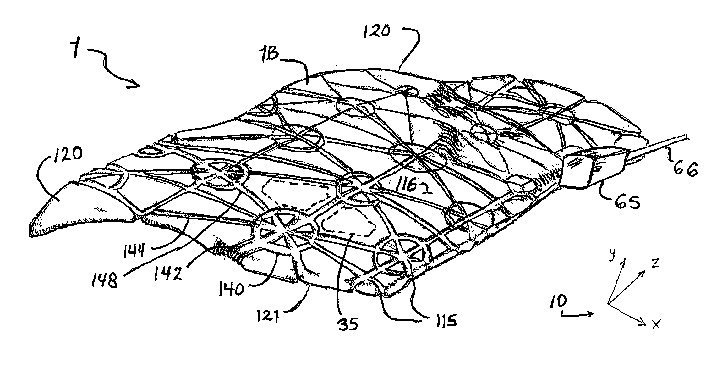
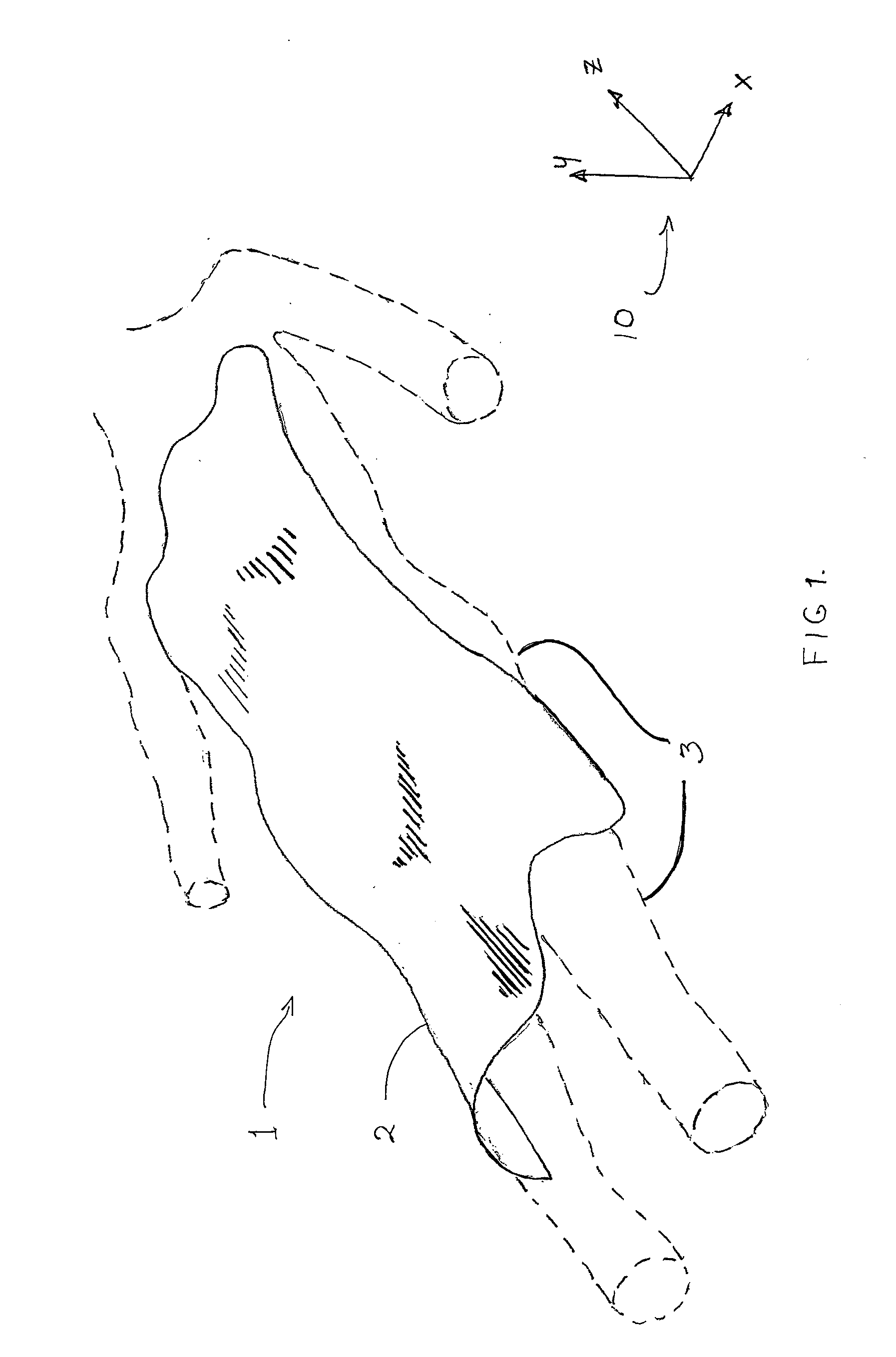
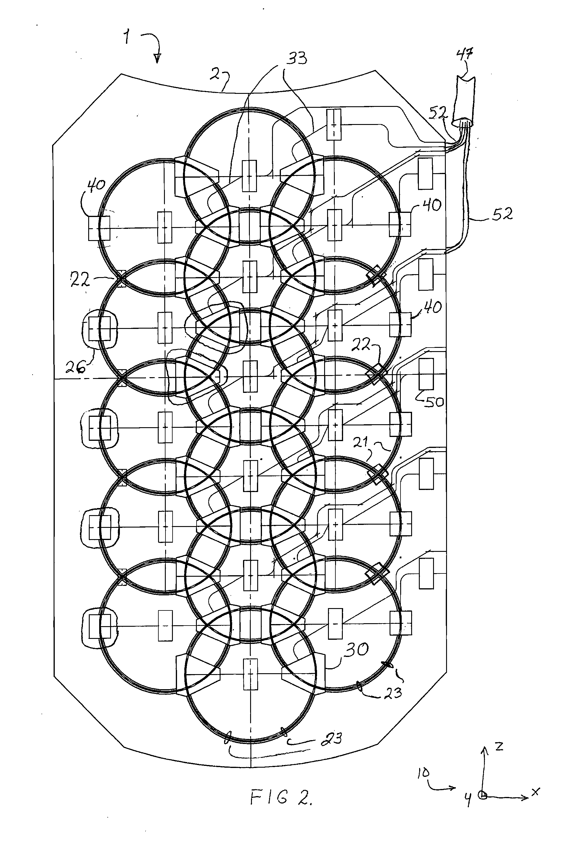
[0055]Referring to FIG. 1, a flexible blanket MRI antenna array in accordance with one embodiment of the present invention is shown generally as 1. The blanket array 1 includes sixteen flexible antenna elements (two of which are identified in FIG. 2 as 21) attached to a flexible substrate 2 that is similar to a thin blanket. The elements 21 and substrate 2 are encapsulated by a flexible housing 1B (FIGS. 5A-B), which is preferably constructed from foam and / or fabric as discussed in more detail below, in such a manner that the entire blanket array 1 is sufficiently flexible to drape over or be wrapped about a human body 3 and distort in three dimensions to closely conform to contours of the body 3. This positions the elements 21 closer to the human tissue where they maintain more constant electromagnetic loading and yield more consistent performance results. Consistency is also improved by ensuring a minimum distance between the actual elements 21 and the target anatomy since signal ...


PUM


Abstract

An MRI antenna array including a housing and a substrate, antenna elements and circuitry encapsulated by the housing. The housing, antenna elements, and substrate are flexible to allow the housing to distort in three dimensions to closely conform to contours of a patient. The antenna elements are mounted to the substrate in a manner that permits each element to maintain a desired resonance when the housing is distorted in three dimensions. The circuitry is electrically coupled with the antenna elements to maintain tuning and isolation of the elements when the housing is distorted in three dimensions. The housing, antenna elements, and substrate may be elastic to allow the housing to be worn by a plurality of different sized patients so that the housing is in close contact with the patient and conforms to contours of the patient.

Description

CROSS-REFERENCE TO RELATED APPLICATIONS[0001]This application is based on and claims priority to U.S. Provisional Application Ser. No. 61 / 563,413, filed on Nov. 23, 2011, which is incorporated herein by reference in its entirety.STATEMENT REGARDING FEDERALLY SPONSORED RESEARCH OR DEVELOPMENT[0002]Not Applicable.BACKGROUND OF THE INVENTION[0003]1. Field of the Invention[0004]The present invention relates generally to magnetic resonance imaging (MRI), and more particularly to flexible and / or elastic MRI antenna arrays for use in receiving MRI signals.[0005]2. Description of Related Art[0006]A. Magnetic Resonance Imaging[0007]Magnetic resonance imaging (MRI) refers generally to a form of clinical imaging based upon the principles of nuclear magnetic resonance (NMR). Any nucleus which possesses a magnetic moment will attempt to align itself with the direction of a magnetic field, the quantum alignment being dependent, among other things, upon the strength of the magnetic field and the m...

Claims


Application Information

Patent Timeline
IPC IPC(8): A61B5/055
CPCA61B5/055G01R33/34007G01R33/3657G01R33/3415G01R33/34084A61B5/6804G01R33/34
Inventor JONES, RANDALL W.
Owner SCANMED
Why Eureka
Try Eureka