Power Sub-grid Including Power Generated From Alternative Sources

Inactive Publication Date: 2013-07-11
PAN YANG
View PDF0 Cites 33 Cited by
  • Summary
  • Abstract
  • Description
  • Claims
  • Application Information

AI Technical Summary

Benefits of technology

[0009]It is another object of the present invention to enable consumption units coupled to the s

Problems solved by technology

However, the generated AC power cannot be distributed by a conventional power grid or be consumed directly by electrical appliances because the generated AC p

Method used


Image

  • Power Sub-grid Including Power Generated From Alternative Sources
  • Power Sub-grid Including Power Generated From Alternative Sources
  • Power Sub-grid Including Power Generated From Alternative Sources

Examples


Example

[0021]The present invention will now be described in detail with references to a few preferred embodiments thereof as illustrated in the accompanying drawings. In the following description, numerous specific details are set forth in order to provide a thorough understanding of the present invention. It will be apparent, however, to one skilled in the art, that the present invention may be practiced without some or all of these specific details. In other instances, well known process steps have not been described in detail in order not to unnecessarily obscure the present invention.

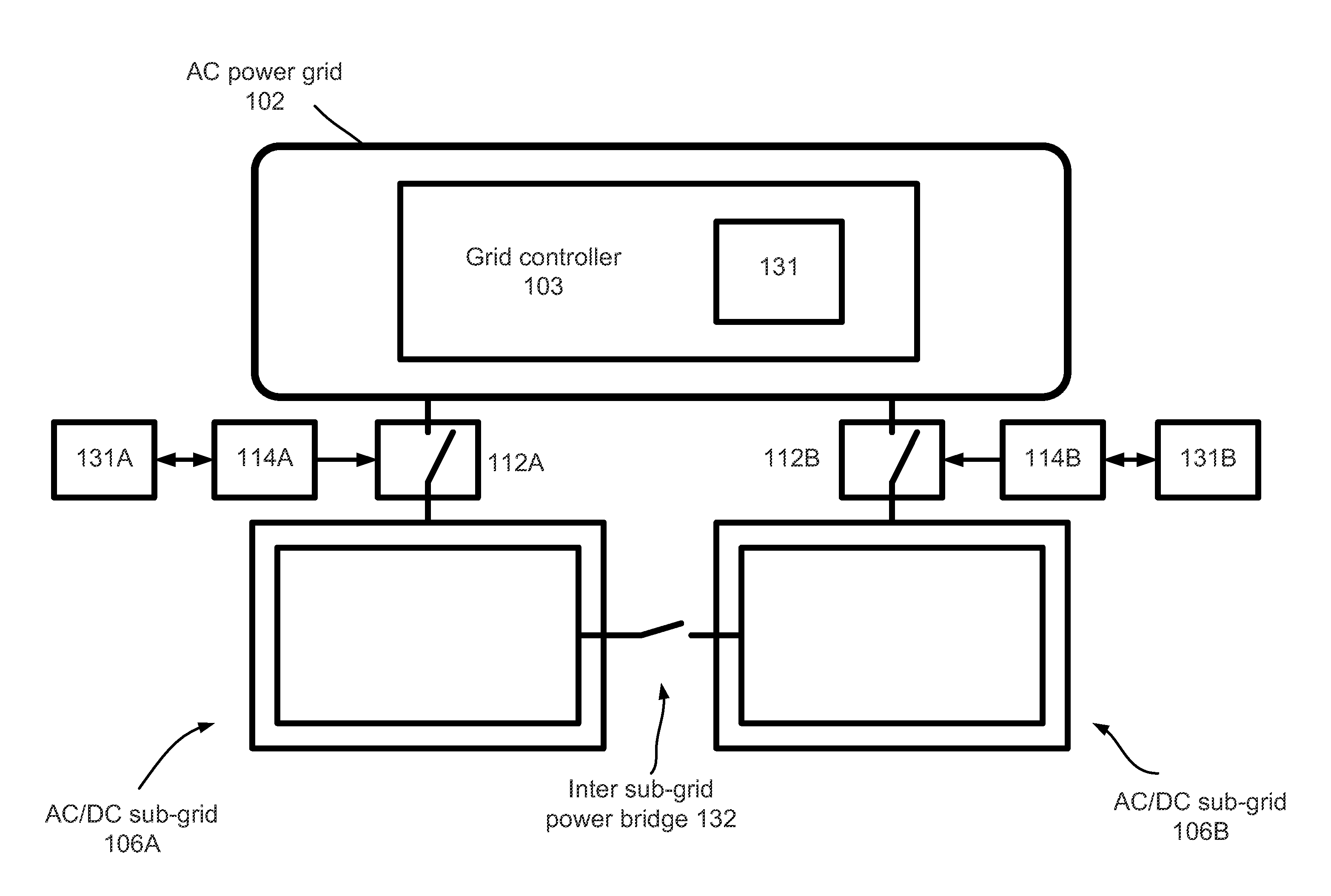
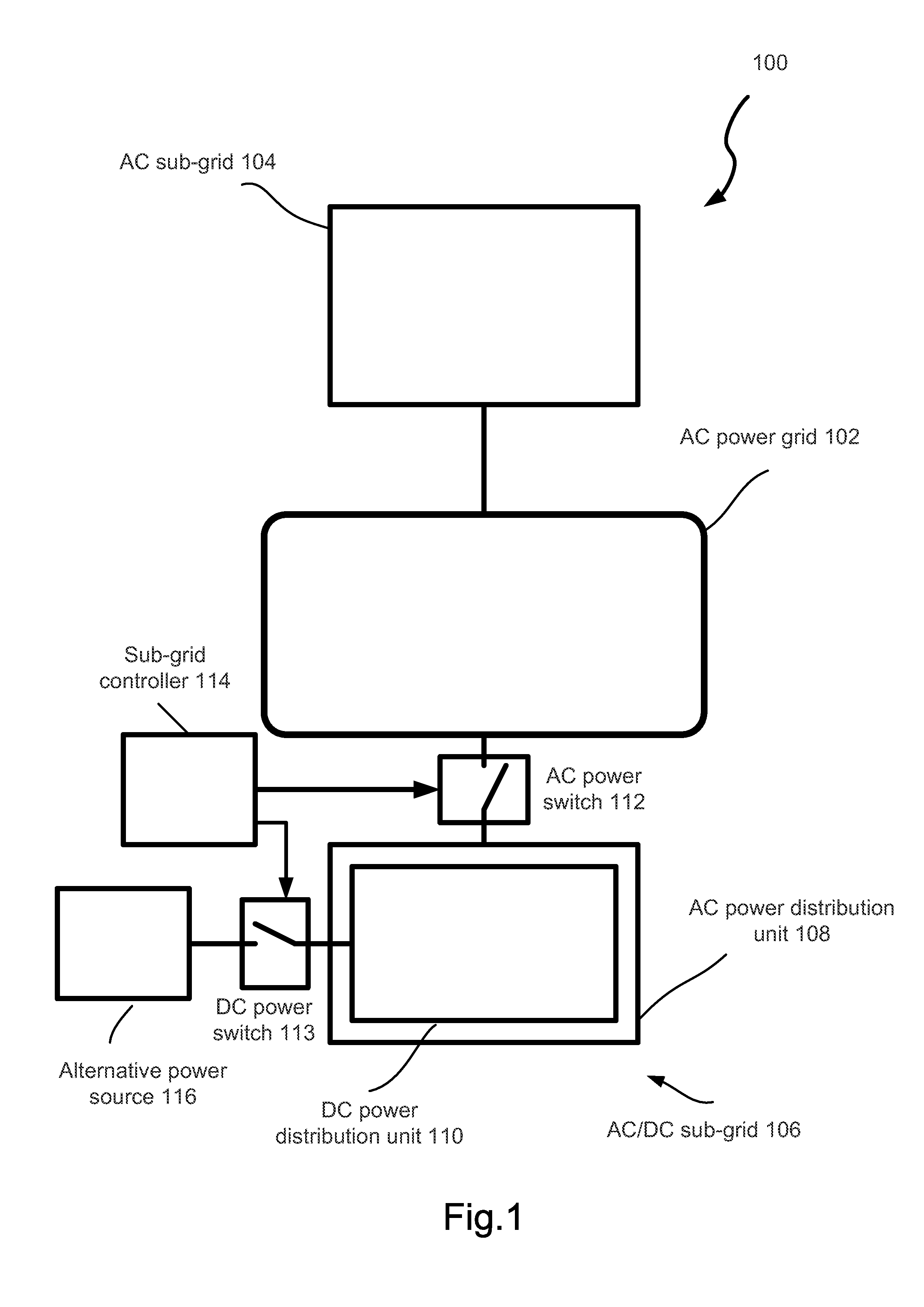
[0022]FIG. 1 is a schematic diagram of an exemplary power distribution system including an AC power grid and at least one exemplary AC / DC sub-grid. Exemplary power distribution system 100 comprises an AC power grid 102. A conventional AC sub-grid 104 is connected to AC power grid 102. AC / DC sub-grid 106 is coupled to AC power grid 102. Sub-grid 106 further includes an AC power distribution unit 108. AC pow...


PUM


Abstract

A power sub-grid for distributing both AC and DC powers is disclosed. A controller selects one of the operation modes for the sub-grid. The operation modes include 1) distributing AC power only; 2) distributing DC power only; and 3) distributing both AC and DC powers. The controller selects the operation mode based upon available DC power generated from alternative sources coupled to the sub-grid and required power for AC and DC electrical appliances in all consumption units. An inter sub-grid power bridge may be used to deliver surplus DC power to another sub-grid.

Description

CROSS-REFERENCE TO RELATED APPLICATIONS[0001]Not applicableBACKGROUND[0002]1. Field of Invention[0003]This invention relates to a power distribution system, specifically to a power sub-grid including alternative power generation sources.[0004]2. Description of Prior Art[0005]In recent years, concerns have been raised that high demand for electricity taxing the capacity of existing electricity generating plants. Furthermore, concerns regarding the availability and environmental safety of fossil and nuclear fuel are being raised. As a result of the above factors, the price of electricity has been on a path of steady increasing. It has become increasing common to seek for alternative power sources. One such power source is the sun. Solar panels have been available for many years for the purpose of converting the energy from sunlight into electricity. The collected energy is in a form of DC (Direct Current) electricity. Another such power source is wind turbines. The electrical power ge...

Claims


Application Information

Patent Timeline
IPC IPC(8): H02J1/00H02J3/00
CPCH02J1/14G06Q50/06G06Q10/06H02J3/382H02J2300/20H02J3/381H02J3/46
Inventor PAN, YANG
Owner PAN YANG
Why Eureka
Try Eureka