Dimming driving system and dimming controller

Active Publication Date: 2013-05-30
LEADTREND TECH
View PDF3 Cites 8 Cited by
  • Summary
  • Abstract
  • Description
  • Claims
  • Application Information

AI Technical Summary

Benefits of technology

[0009]Another embodiment provides a dimming controller formed in an integrated circuit chip. The dimming controller includes a phase truncation control pin, a dimming control pin, and a processing circuit. The phase truncation control pin is coupled to a transformer for receiving a sensing signal. The dimming control pin is used for receiving a dimming signal. The processing c

Problems solved by technology

However, control chips provided by the prior art only can provide one or two of the at least three possible dimming manners.
But, control accuracy of the current flowing through the series of light-emitting

Method used


Image

  • Dimming driving system and dimming controller
  • Dimming driving system and dimming controller
  • Dimming driving system and dimming controller

Examples


Example

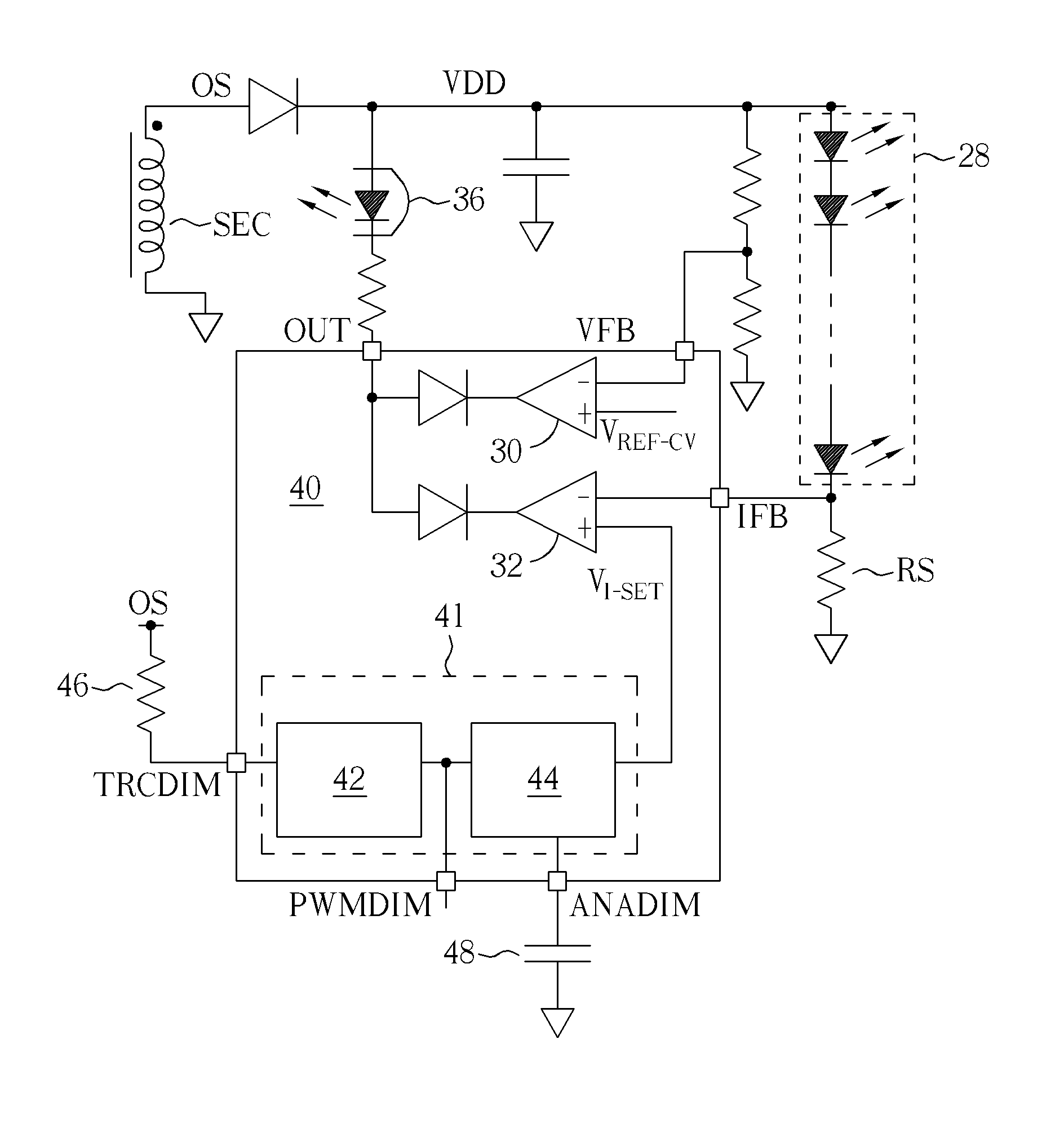
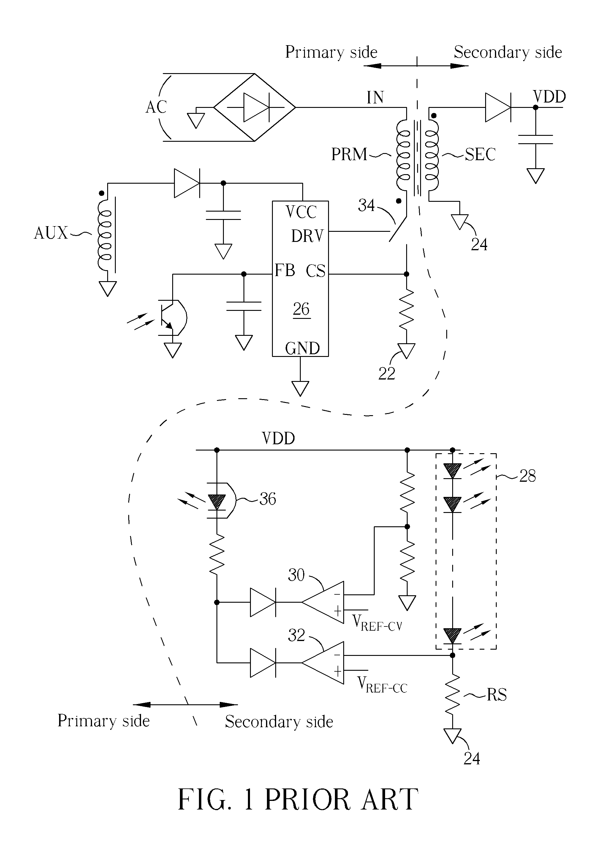
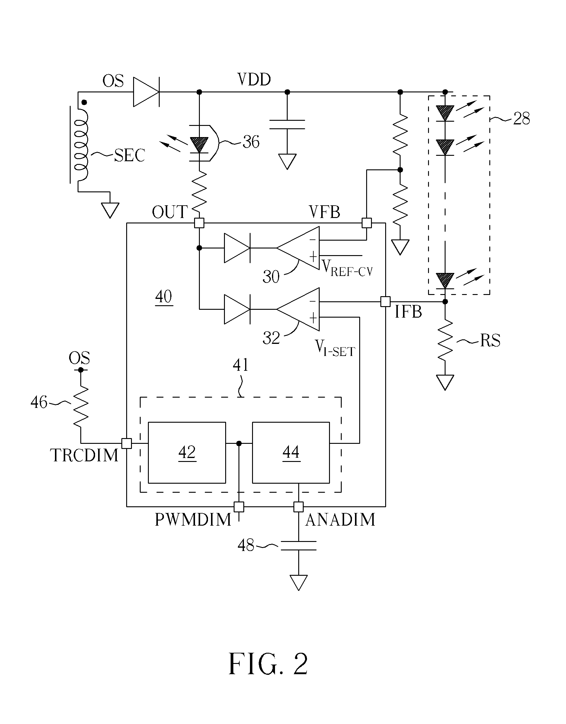
[0019]FIG. 2 is a diagram illustrating a secondary side circuit of a light-emitting diode driving circuit according to an embodiment, where the secondary side circuit can provide a phase truncation (TRIAC) dimming, a pulse-width modulation (PWM) dimming, and an analog level dimming. A primary side circuit not shown in FIG. 2 can be implemented as the primary side circuit shown in FIG. 1 or other well-known primary side circuits by those of ordinary skill in the art, so further description thereof is omitted for simplicity. As shown in FIG. 2, after current flowing through a secondary winding SEC is rectified by a diode, the current can build an output voltage VDD on an output power line VDD. The output power line VDD and a secondary side ground wire 24 can power a series of light-emitting diodes 28 together.

[0020]A dimming controller 40 is shown in FIG. 2. In embodiments of the present invention as follows, the dimming controller 40 is a monolithic integrated circuit chip formed in ...


PUM


Abstract

Disclosed are dimming driving system and a dimming controller. A disclosed dimming driving system has a transformer, a lighting device, and a dimming controller. The transformer has a primary winding and a secondary winding inductively-coupled to each other. The secondary winding is coupled to an output power line and secondary ground, both coupling to and powering the lighting device. The dimming controller is coupled to the secondary winding for controlling current flowing through the lighting device according to a voltage drop of the secondary winding.

Description

BACKGROUND OF THE INVENTION[0001]1. Field of the Invention[0002]The present invention relates to a dimming driving system and a dimming controller, and particularly to a dimming driving system and a dimming controller that can accept a plurality of dimming signals.[0003]2. Description of the Prior Art[0004]A light-emitting diode driving circuit with a dimming function needs to have at least three possible dimming manners: a phase truncation (TRIAC) dimming, a pulse-width modulation (PWM) dimming, and an analog level dimming. However, control chips provided by the prior art only can provide one or two of the at least three possible dimming manners.[0005]FIG. 1 is a diagram illustrating a light-emitting diode driving circuit according to the prior art, where the light-emitting diode driving circuit has a flyback topology, a transformer of the light-emitting diode driving circuit has a primary winding PRM, a secondary winding SEC, and a auxiliary winding AUX inductively coupled to each...

Claims


Application Information

Patent Timeline
IPC IPC(8): H05B33/08H05B44/00
CPCH05B33/0845Y02B20/347H05B33/0815H05B45/382Y02B20/30H05B45/385H05B45/10
Inventor YAU, YEU-TORNGHUANG, KUO-CHIEN
Owner LEADTREND TECH
Why Eureka
Try Eureka