

Electrically powered garden tool
a technology of electric power and garden tools, applied in the field of electric power garden tools, can solve the problems of operator operator also situated in an unpleasant condition, and inability to reduce blowing noise, so as to improve the working condition of the operator and reduce the blowing noise of exhaust air
- Summary
- Abstract
- Description
- Claims
- Application Information
AI Technical Summary
Benefits of technology
Problems solved by technology
Method used
Image

Examples
first embodiment
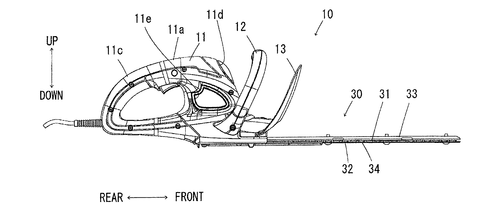
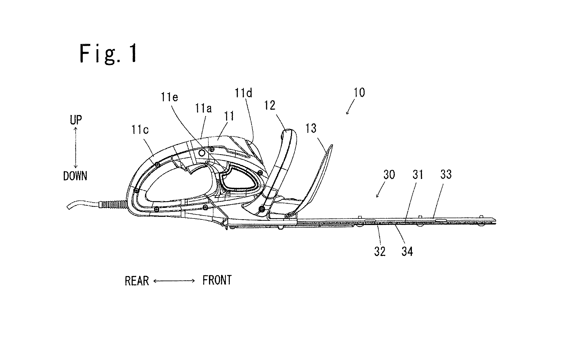
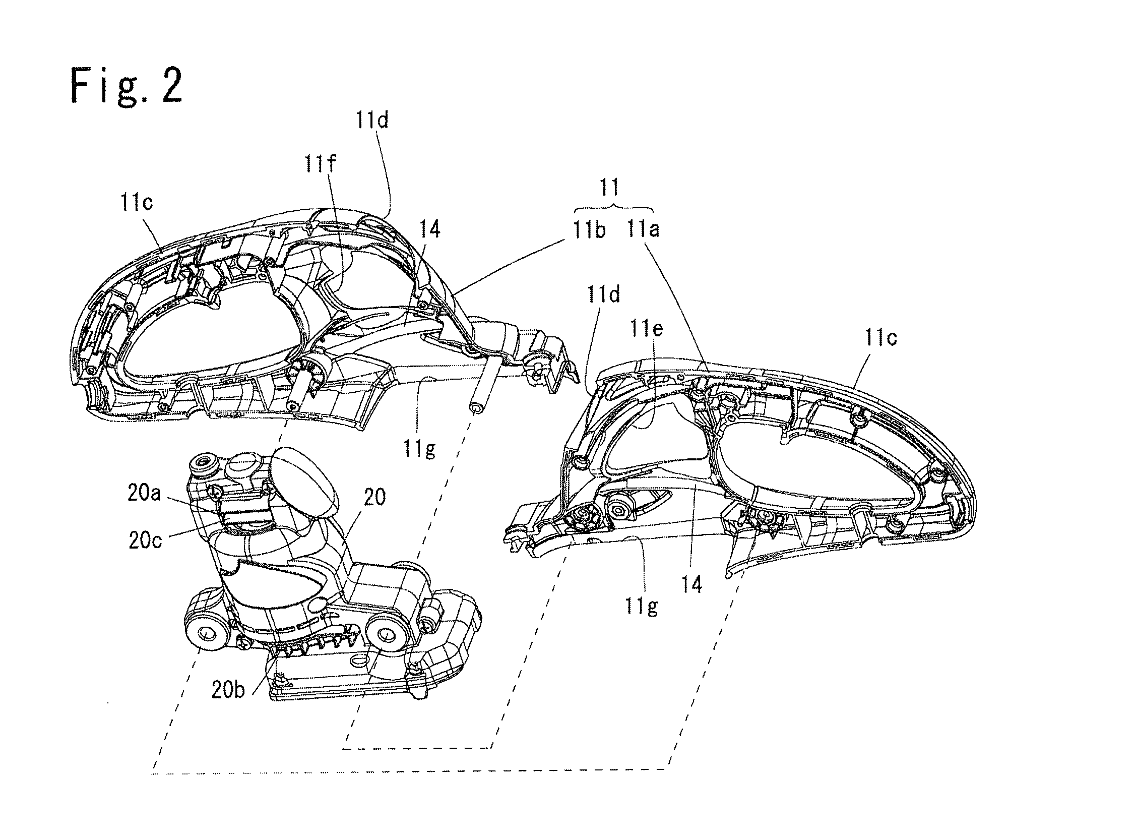
[0020]As shown in FIGS. 1-4, an electrically powered hedge trimmer 10 of the present invention includes an electric motor 21 mounted upright within an outer shell housing 11, a pair of relatively reciprocating shear blades 31, 32 assembled within a lower portion of the outer shell housing 11 to be driven by operation of the electric motor 21 through a crank mechanism 23, and a cooling fan 22 assembled to be driven by rotation of the motor 21 for introducing outside air into an upper portion of shell housing 11 and for blowing out the sucked air from a lower portion of the shell housing 11. In this hedge trimmer 10, as shown in FIG. 4, a downward opening 11g is formed in a lower portion of the peripheral wall of shell housing 11 enclosing a side portion of the crank mechanism 23 such that the air exhausted by operation of the cooling fan 22 flows along an inner surface of the lower peripheral wall of shell housing 11 and blows out downward from the downward opening 11g. In addition, ...
second embodiment
[0032]In a hedge trimmer 10A shown in FIG. 6, the electric motor 21, cooling fan 22 and crank mechanism 23 are assembled within an outer shell housing 11A without the motor housing 20. In the hedge trimmer 10A, an air intake opening 11Ah is formed in the upper peripheral wall of outer shell housing 11A for introducing outside air therein during operation of the cooling fan, and an exhaust opening 11Ag is formed within the lower end peripheral wall of outer shell housing 11A. The exhaust opening 11Ag is opened downward without any obstacle in the exhaust passage as in the first embodiment. The noise absorption element 14 is attached to an inner surface of outer shell housing 11A exposed to the air spouted from the cooling fan 22 there by to restrain blowing noise caused by deflection of the spouted air.
[0033]Assuming that the cooling fan 22 is operated by activation of the electric motor 21, the outside air is introduced into the upper portion of outer shell housing 11A through the a...
PUM
 Abstract
Description
Claims
Application Information