Optical cable dryer

A technology of blow dryer and optical cable, which is applied in the direction of drying, drying machine, drying gas arrangement, etc. It can solve the problems of excessive noise in the workshop, increased noise of workshop equipment, and increase in the number of compressor unit equipment, etc., to achieve large market development and Promote value, reduce water blowing noise, and facilitate installation

Active Publication Date: 2014-12-10
FENGHUO COMM SCI & TECH CO LTD +1
View PDF5 Cites 0 Cited by
  • Summary
  • Abstract
  • Description
  • Claims
  • Application Information

AI Technical Summary

Problems solved by technology

[0003] In the high-speed manufacturing process of leather cables and single-core cables, after the optical cables come out of the cooling water tank, there will be water on the surface of the optical cables, especially shaped optical cables (figure-eight cables, leather cables), which have grooves in the middle and a large amount of water. , the old-fashioned water blower can not meet the production needs very well, the printing is often unclear, the printing tape sticks to the surface of the optical cable, and then wraps around the traction wheel, resulting in a series of problems such as equipment damage and excessive noise in the workshop. Optical cables sheathed with smoke-free halogen materials, when inkjet printing on the surface, often cause the printed characters to be unclear or fall off due to water on the surface of the cable. are indispensable
[0004] At present, optical cable manufacturers have increased the production speed, and the drying of optical cables has become a big problem. Now some manufacturers mainly solve the problem of water blowing by increasing the air volume, which directly leads to a rapid increase in the number of compressor units. At the same time The noise of workshop equipment increases significantly, causing different degrees of noise pollution to the workshop environment

Method used


Image

  • Optical cable dryer
  • Optical cable dryer
  • Optical cable dryer

Examples


Embodiment Construction

[0026] The present invention will be further described in detail below in conjunction with the accompanying drawings and specific embodiments.

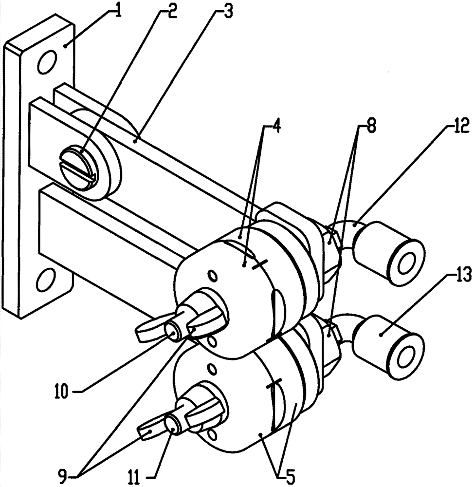
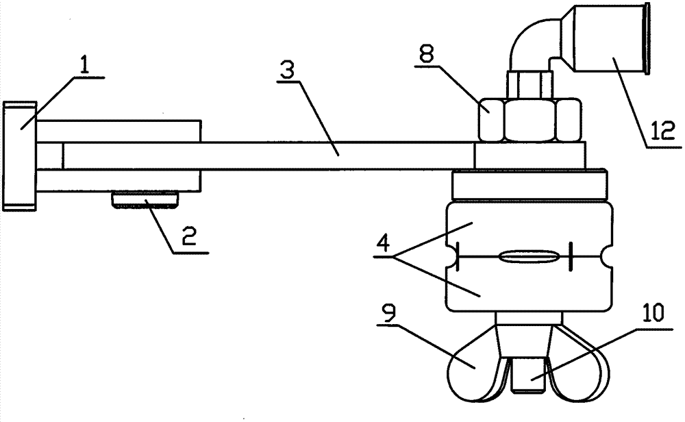
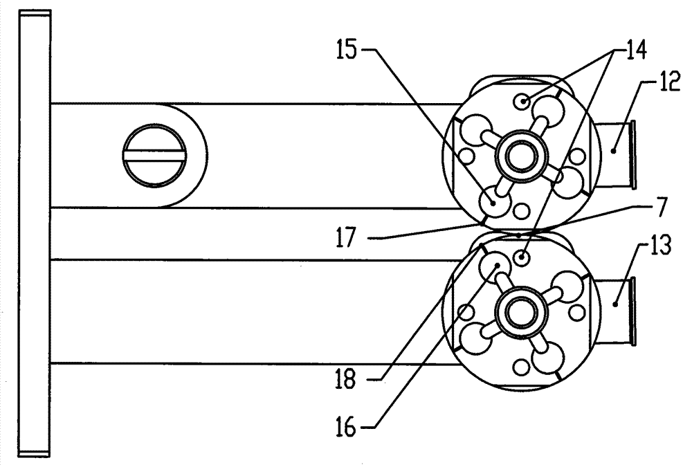
[0027] see figure 1 As shown, the fiber optic cable blower provided by the embodiment of the present invention includes a blower bracket, four water blowing boxes (two upper water blowing boxes 4, two lower water blowing boxes 5), an upper air inlet bend Head 12 and lower intake elbow 13, the dryer bracket includes a mounting plate 1, a movable pole 3 and a fixed pole, one end of the fixed pole is fixed on the mounting plate 1, and the end of the movable pole 3 is close to the mounting plate 1 It is connected with the mounting plate 1 through the hinge screw 2, which is convenient to operate during production. When the optical cable product produced is larger than the design diameter, the movable support rod 3 can be automatically lifted under the action of inertia to prevent damage to the equipment and the optical cable.

[0028] se...


PUM


Abstract

The invention discloses an optical cable dryer. The optical cable dryer comprises a dryer bracket, four water blowing box bodies and two gas inlet bends, wherein the dryer bracket comprises an installation plate, a movable supporting board and a fixed supporting rod; one end of the fixed supporting rod and one end of the movable supporting rod are respectively connected with the installation plate; the four water blowing box bodies are in hollow cylindrical structures with 2-8 notches on outer edges; 2-8 gas blowing holes are formed on each cylinder along the radial direction correspondingly; the gas blowing holes of the two upper water blowing box bodies are abutted to form an upper water blowing box which is fixed on one end, far from the installation plate, of the movable supporting rod; the gas blowing holes of the two lower water blowing box bodies are abutted to form a lower water blowing box which is fixed on one end, far from the installation plate, of the fixed supporting rod; and notches on the contact part of upper and lower water blowing boxes form guide holes. The optical cable dryer has light weight, small size, high efficiency, little consumed gas, small noise, convenience in installation and simplicity in operation, is energy-saving and environment-friendly, and capable of effectively solving the problems that a traction wheel is wound by a print band, the device is damaged, inkjet printing is fuzzy and product appearance is affected as the surface of the optical cable contains water.

Description

technical field [0001] The invention relates to the field of optical cable manufacture, in particular to an optical cable blower. Background technique [0002] With the continuous advancement of China's modernization process and the development of optical communications, especially the development of access networks and the advancement of triple play, optical cables have been more widely used. There are thousands of optical cable manufacturers, and market competition is increasing. Intense, with the maturity of optical cable design and manufacturing process, customers have higher and higher requirements for product quality and appearance. At the same time, the appearance of the product is also the image of the company. In order to reduce costs and enhance competitiveness, major manufacturers can be said to have their own special skills. Most of them increase production speed, increase production efficiency and increase production capacity to achieve cost reduction. Purpose....

Claims


Application Information

Patent Timeline
Patent Type & Authority Patents(China)
IPC IPC(8): F26B21/00G02B6/44
Inventor 王新强吴忠明郑阳廖伟章曾志陈涛
Owner FENGHUO COMM SCI & TECH CO LTD
Why Eureka
Try Eureka