
Electrically powered garden tool

a technology of electric power and garden tools, applied in the field of electric power garden tools, can solve the problems of operator operator also situated in an unpleasant condition, and inability to reduce blowing noise, so as to improve the working condition of the operator and reduce the blowing noise of exhaust air

Active Publication Date: 2015-08-11
MAKITA CORP
View PDF13 Cites 2 Cited by
  • Summary
  • Abstract
  • Description
  • Claims
  • Application Information

AI Technical Summary

Benefits of technology

This design improves operator comfort by reducing blowing noises and enhancing exhaust efficiency, directing air exhaust downward away from the operator and reducing noise impact.

Problems solved by technology

When the electric motor of the hedge trimmer is activated to impart reciprocal motion to the shear blades and to rotate the cooling fan, an operator is situated in an unpleasant condition caused by the blow of air exhausted laterally from the exhaust opening of the lower peripheral wall of the outer shell housing.
The operator is also situated in an unpleasant condition caused by blow noises of the exhaust air and driving noises transmitted from the crank mechanism during reciprocal motion of the shear blades.
Due to such blow of the exhaust air, it is unable to reduce blowing noises of the air exhausted from the lower end opening of the outer shell housing and to reduce driving noises caused by reciprocal motion of the shear blades.

Method used


Image

  • Electrically powered garden tool
  • Electrically powered garden tool
  • Electrically powered garden tool

Examples


first embodiment

[0020]

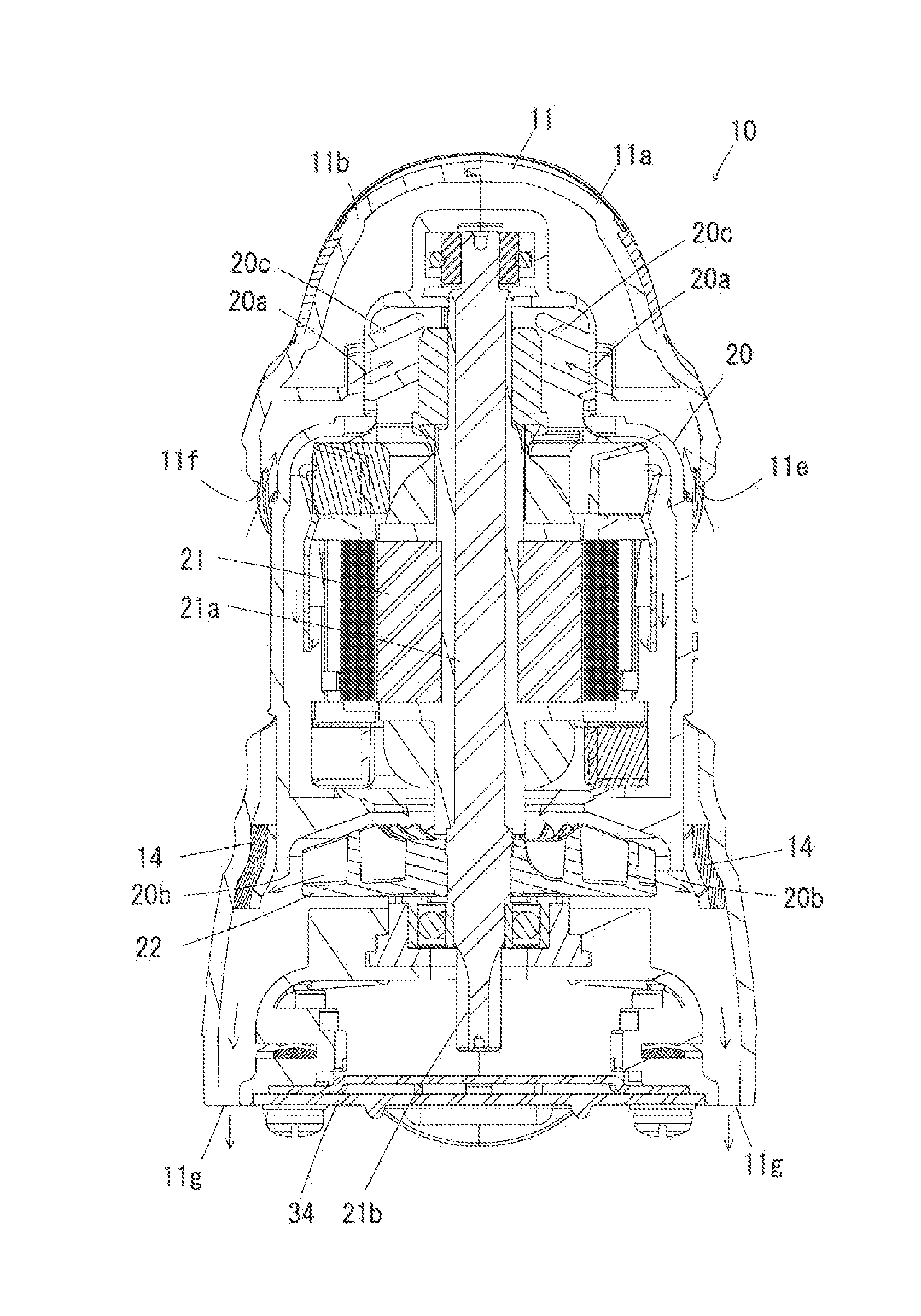
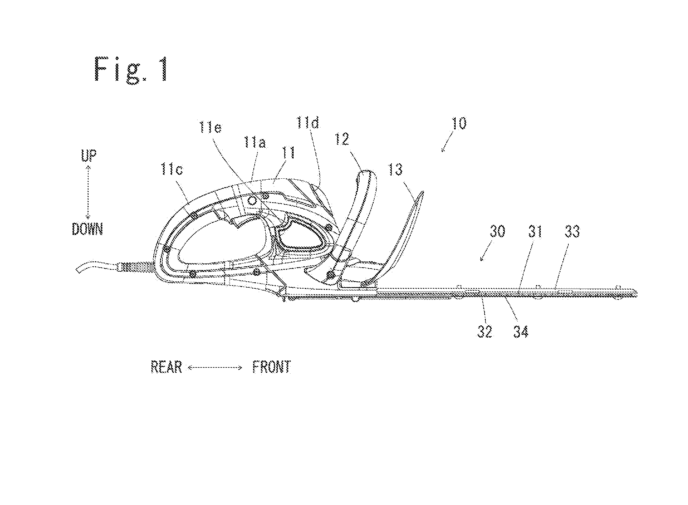
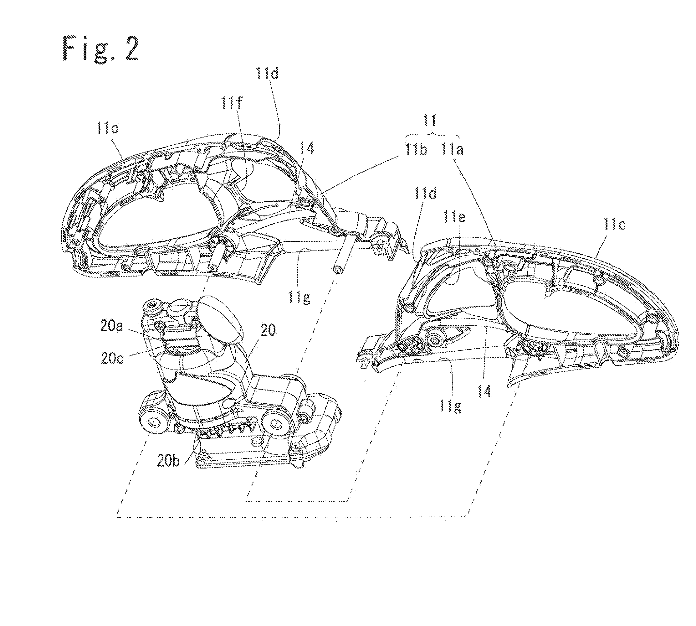
[0021]As shown in FIGS. 1-4, an electrically powered hedge trimmer 10 of the present invention includes an electric motor 21 mounted upright within an outer shell housing 11, a pair of relatively reciprocating shear blades 31, 32 assembled within a lower portion of the outer shell housing 11 to be driven by operation of the electric motor 21 through a crank mechanism 23, and a cooling fan 22 assembled to be driven by rotation of the motor 21 for introducing outside air into an upper portion of shell housing 11 and for blowing out the sucked air from a lower portion of the shell housing 11. In this hedge trimmer 10, as shown in FIG. 4, a downward opening 11g is formed in a lower portion of the peripheral wall of shell housing 11 enclosing a side portion of the crank mechanism 23 such that the air exhausted by operation of the cooling fan 22 flows along an inner surface of the lower peripheral wall of shell housing 11 and blows out downward from the downward opening 11g. In addi...

second embodiment

[0033]

[0034]In a hedge trimmer 10A shown in FIG. 6, the electric motor 21, cooling fan 22 and crank mechanism 23 are assembled within an outer shell housing 11A without the motor housing 20. In the hedge trimmer 10A, an air intake opening 11Ah is formed in the upper peripheral wall of outer shell housing 11A for introducing outside air therein during operation of the cooling fan, and an exhaust opening 11Ag is formed within the lower end peripheral wall of outer shell housing 11A. The exhaust opening 11Ag is opened downward without any obstacle in the exhaust passage as in the first embodiment. The noise absorption element 14 is attached to an inner surface of outer shell housing 11A exposed to the air spouted from the cooling fan 22 there by to restrain blowing noise caused by deflection of the spouted air.

[0035]Assuming that the cooling fan 22 is operated by activation of the electric motor 21, the outside air is introduced into the upper portion of outer shell housing 11A through...


PUM


Abstract

An electrically powered garden tool includes an electric motor mounted upright within an outer shell housing, a pair of relatively reciprocating shear blades assembled to be driven by operation of the motor through a crank mechanism provided within a lower portion of the outer shell housing, and a cooling fan assembled to be driven by operation of the motor for introducing outside air into an upper portion of the outer shell housing to exhaust the introduced air from a lower portion of the outer shell housing. In the garden tool, a downward exhaust opening is formed within a lower end peripheral wall of the outer shell housing enclosing the crank mechanism such that the air spouted by rotation of the cooling fan blows out downward from the downward exhaust opening to restrain the occurrence of blowing noise of the air.

Description

BACKGROUND OF THE INVENTION[0001]1. Field of the Invention[0002]The present invention relates to electrically powered garden tools such as a power-operated hedge trimmer, an electrically powered grass shear and the like.[0003]2. Description of the Prior Art[0004]Disclosed in Japanese Patent Laid-open Publication Nos. 2007-075917 and 2010-094086 is an electrically powered hedge trimmer of the type which includes an electric motor mounted upright within an outer shell housing, a pair of relatively reciprocating shear blades assembled to be driven by operation of the motor through a crank mechanism provided within a lower portion of the outer shell housing, and a cooling fan assembled to be driven by operation of the motor for introducing outside air from an intake opening formed in an upper peripheral wall of the outer shell housing and for exhausting the sucked air from an opening laterally formed in a lower peripheral wall of the outer shell housing.[0005]When the electric motor of ...

Claims


Application Information

Patent Timeline
Patent Type & Authority Patents(United States)
IPC IPC(8): A01G3/053A01G3/06A01G3/04
CPCA01G3/067A01G3/053A01G2003/0461
Inventor KATO, KAZUYATAKANO, HIDEAKIKOIDE, YUKI
Owner MAKITA CORP
Learn More