Intrinsically-calibrated tribometer

a tribometer and internal calibration technology, applied in the field of test measurement, can solve the problems of large variability in the measured value of “static” friction, severe impairment of mobility, general health, and inability to reliably produce the theoretically expected horizontal and vertical force components,

Active Publication Date: 2014-01-16
JOHNSON FRED M
View PDF14 Cites 3 Cited by
  • Summary
  • Abstract
  • Description
  • Claims
  • Application Information

AI Technical Summary

Problems solved by technology

These accidents are particularly serious for the elderly, who may suffer a fall injury that severely impairs their mobility, independence, and general health.
Application of the First Law of Thermodynamics to the mechanics of impact devices shows that these devices dissipate some amount of kinetic energy during mensuration, causing wide variability in the measured value of “static” friction.
In fact, “impact devices” that rely on gravity, on spring loaded pressure, or on pneumatic pressure are actually energy converters that tend not to reliably produce their theoretically expected horizontal and vertical force components.
Moreover, each of the “pull”-type devices use a respective test material (neolite, neoprene / rubber) that is generally unrepresentative of materials used by an actual pedestrian.
A difficulty in reported and published measurements derived from impact and pull devices alike is that the devices produce divergent numerical values for their output.

Method used


Image

  • Intrinsically-calibrated tribometer
  • Intrinsically-calibrated tribometer
  • Intrinsically-calibrated tribometer

Examples


Embodiment Construction

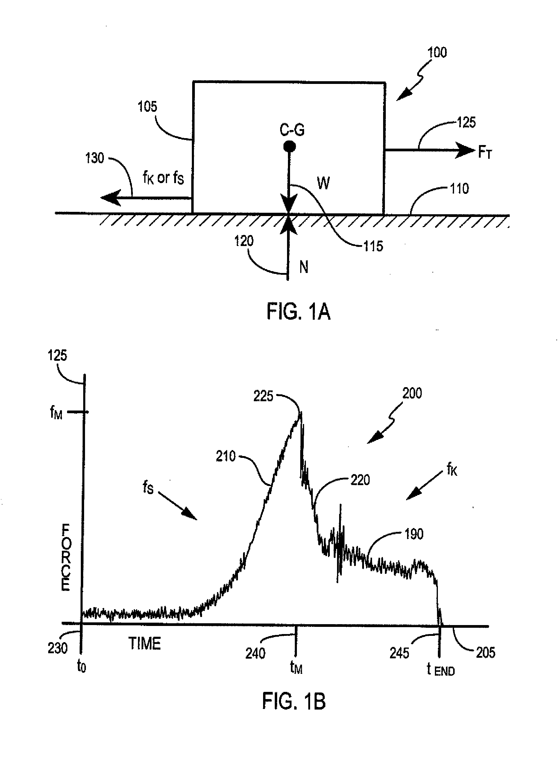
[0025]FIGS. 1A and 1B are physical and frictional models, respectively, which illustrate the principles of the embodiments described herein. FIG. 1A depicts a physical model 100 having two elements 105, 110 in frictional contact. In general, model 100 can be illustrated with a surface of first element 105 being disposed second element 110. First element 105 may be a test material. Second element 110 may be a test surface. Second surface 110 is depicted as being substantially horizontal, relative to gravitational force G (115). On a terrestrial surface (e.g., an x, y plane in an x, y, z space), first element 105 experiences normal force N 120 opposing gravitational force G 115. In general, normal force N 120 is produced at a right angle (90°) to the mutual interface between first element 105 and second element 110, that is, where the opposing surfaces of first element 105 and second element 110 meet. When tangential force F 125, which is depicted as substantially horizontal, is gradu...


PUM

PropertyMeasurementUnit
propulsion forceaaaaaaaaaa
tractive forceaaaaaaaaaa
propulsionaaaaaaaaaa

Abstract

Intrinsically calibrating friction mensuration device has a drive unit with controllable motive member, configured to receive a controllable propulsion force, and to apply tractive force to a test piece on a surface. A force engine couples to the motive member, and applies the controllable propulsion force. The device includes a controller imposing a propulsion control signal actuating the force engine to produce the propulsion force. A force sensor is between the drive unit and the test piece, producing a force signal responsive to a sensed force between the drive unit and the test piece. The drive unit can self-propelled or stationary. A method includes applying an increasing tractive force to a test piece at rest; measuring the tractive force; identifying the maximum tractive force applied at incipient motion; identifying the transition between the resting test piece and incipient motion; determining the SCOF; continue motion and determine the DCOF.

Description

BACKGROUND OF THE INVENTION[0001]1. Field of the Invention[0002]The present invention relates generally to the field of test measurement and more particularly to friction mensuration devices and most particularly to tribometers.[0003]2. Background Art[0004]Over one million people experience slip, trip, or fall accidents each year and approximately 17,000 die from the resultant fall injuries, second only to the number of automobile accident fatalities. These accidents are particularly serious for the elderly, who may suffer a fall injury that severely impairs their mobility, independence, and general health. These accidents can and do occur in a wide range of environments, including construction sites, private residences, playgrounds and recreational facilities, industrial settings, public and private property (e.g., sidewalks, highways roadways, streets, parking lots, markets); public transportation facilities (airports, subways, train & bus stations) and facilities for the elderly ...

Claims


Application Information

Patent Timeline
Patent Type & Authority Applications(United States)
IPC IPC(8): G01N19/02
CPCG01N19/02
Inventor JOHNSON, FRED M.
Owner JOHNSON FRED M
Why Eureka
Try Eureka