Symmetrical hybrid coupler

a hybrid coupler and symmetrical technology, applied in the direction of coupling devices, waveguide type devices, basic electric elements, etc., can solve the problems of reducing the overall size of the device, affecting the performance of the device, and the cancellation is not perfect, so as to achieve high coupling and symmetry, improve power handling, and reduce the volume

Active Publication Date: 2014-03-27
TTM TECH INC
View PDF0 Cites 19 Cited by
  • Summary
  • Abstract
  • Description
  • Claims
  • Application Information

AI Technical Summary

Benefits of technology

[0015]The present invention is directed to a symmetrical hybrid coupler that addresses the needs described above. In particular, the symmetrical hybrid coupler of the present invention achieves high coupling and symmetry in a smaller volume. Moreover, the device of the present invention provide improved power handling and lower thermal resistivity in the z-plane.

Problems solved by technology

However, the coupler usually has an “insertion loss” which accounts for the differences between the input signal and the output signals.
At the isolation port, there is destructive interference of RF waves and the RF signals cancel such that there is no appreciable signal available at the fourth port.
In practice, the cancellation is not perfect and a residual signal may be detected.
One of the main challenges that RF design engineers are facing is to reduce the overall size of the device while maintaining the part performance.
Various approaches have been used to reduce coupler size, but each approach has its respective drawbacks.
For example, meandered line structures exhibit an even / odd mode phase velocity imbalance that limits the operational bandwidth.
Moreover, the asymmetry of the line layout results in loss of performance symmetry.
The inter-digital approach has been considered as a means to achieve high coupling in smaller volume, however, it does not have the desired symmetry.

Method used


Image

  • Symmetrical hybrid coupler
  • Symmetrical hybrid coupler
  • Symmetrical hybrid coupler

Examples


Embodiment Construction

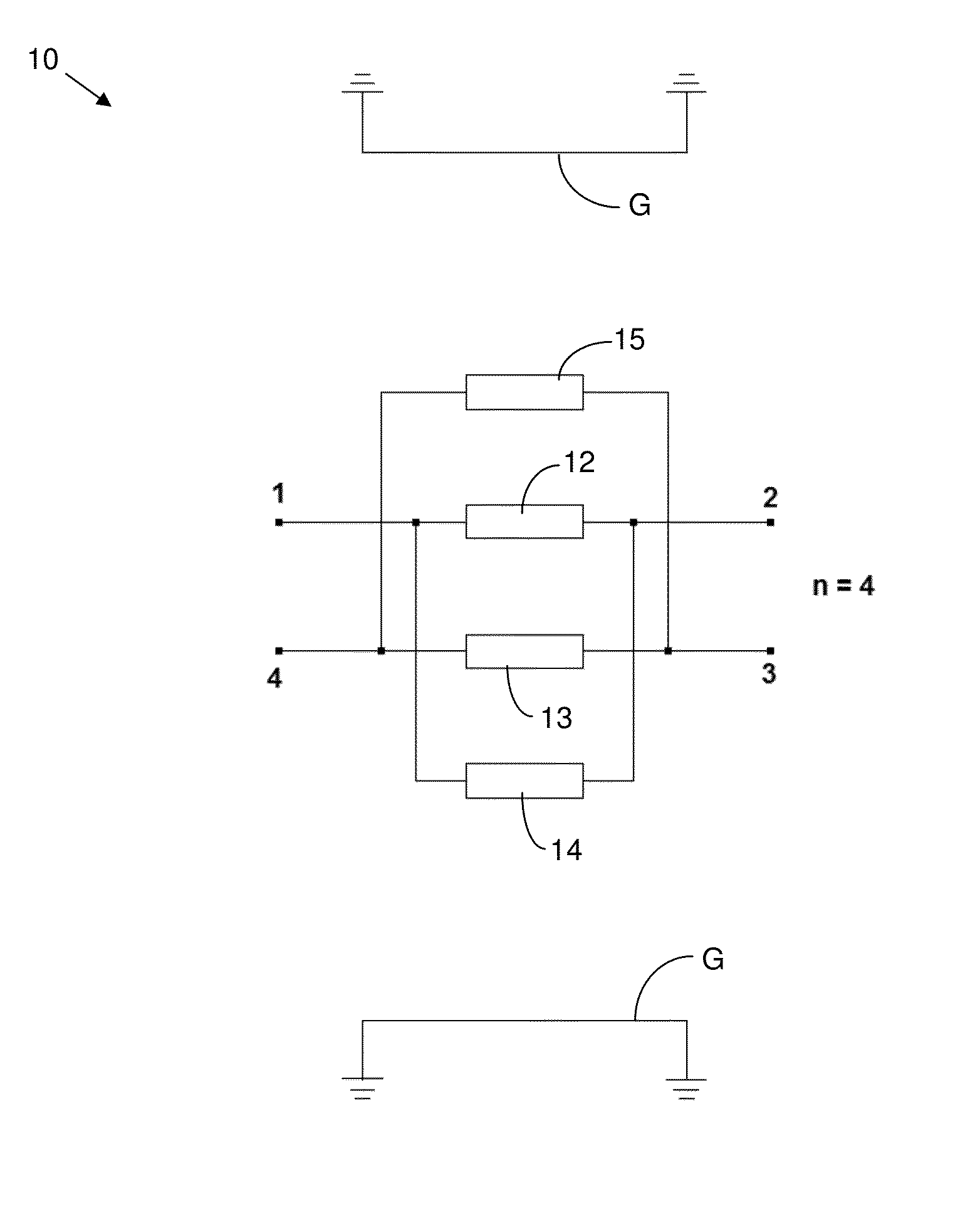
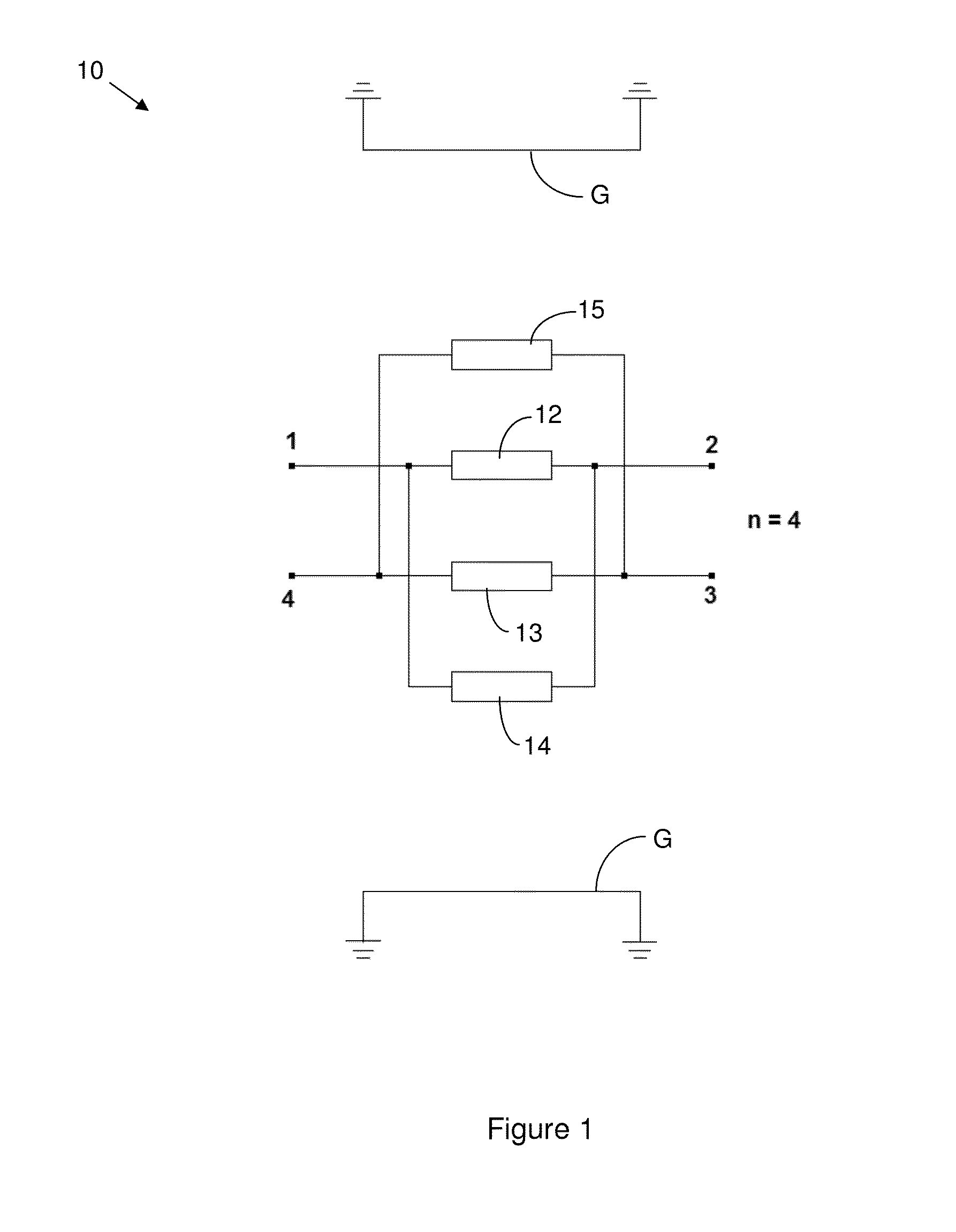
[0028]Reference will now be made in detail to the present exemplary embodiments of the invention, examples of which are illustrated in the accompanying drawings. Wherever possible, the same reference numbers will be used throughout the drawings to refer to the same or like parts. An exemplary embodiment of the coupler of the present invention is shown in FIG. 1.

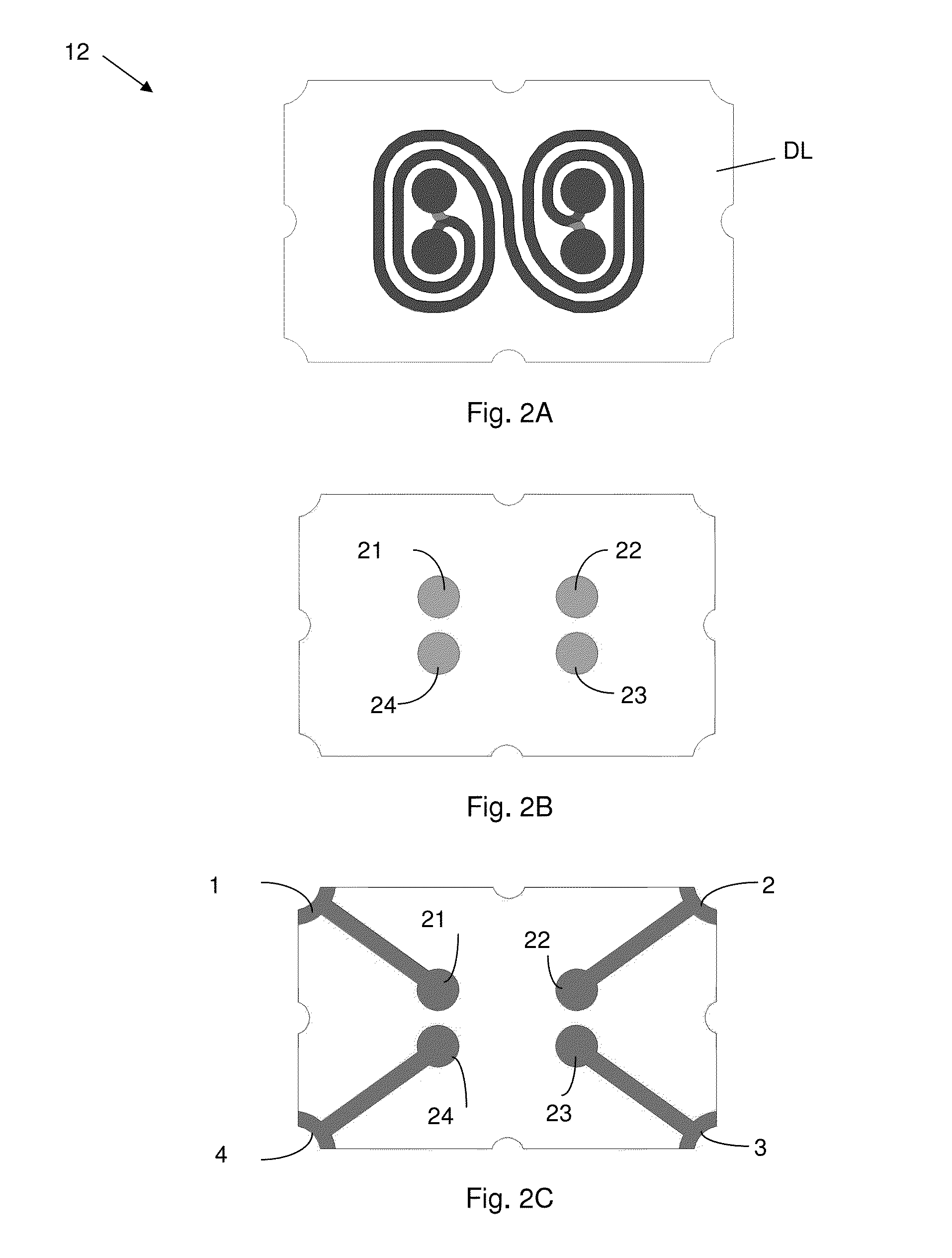
[0029]As embodied herein and depicted FIG. 1 is a schematic diagram of the coupler in accordance with a first embodiment of the present invention is disclosed. In this embodiment of the present invention, the coupler includes four transmission lines that are interdigitally connected to each other. The transmission line 12 is interconnected between port 1 and port 2. Transmission line 14 is coupled in parallel with transmission line 12. The transmission line 13 is interconnected between port 3 and port 4. Transmission line 15 is coupled in parallel with transmission line 13. The above described coupler structure is disposed be...


PUM


Abstract

The present invention is directed to a hybrid coupler device that includes a first transmission line structure and a second transmission line structure. The first transmission line structure is interdigitally coupled with the second transmission line structure such that each transmission line in the second transmission line structure is disposed adjacent to a transmission line in the first transmission line structure. The coupling or the mutual capacitance Cd between the transmission lines of the present invention need not be equal; in fact, they all can be different.

Description

CROSS-REFERENCE TO RELATED APPLICATIONS[0001]This is related to U.S. Provisional Patent Application Ser. No. 61 / 706,363 filed on Sep. 27, 2012, the content of which is relied upon and incorporated herein by reference in its entirety, and the benefit of priority under 35 U.S.C. §119(e) is hereby claimed.BACKGROUND OF THE INVENTION[0002]1. Field of the Invention[0003]The present invention relates generally Microwave / RF components and more specifically coupled transmission line components.[0004]2. Technical Background[0005]A directional coupler is a four port passive device that is used to combine, split and / or direct an RF signal within an RF circuit in a desired, predictable manner. A coupler can be implemented by placing two transmission lines in relatively close proximity to each other. Directional couplers operate in accordance with the principles of superposition and constructive / destructive interference of RF waves. When splitting a signal, the RF signal directed into the input ...

Claims


Application Information

Patent Timeline
Patent Type & Authority Applications(United States)
IPC IPC(8): H01P5/22
CPCH01P5/184H01P5/187
Inventor MEI, CHONGMUSTACOGLU, HALID
Owner TTM TECH INC
Why Eureka
Try Eureka