Liquid crystal display device

a liquid crystal display and display device technology, applied in non-linear optics, instruments, optics, etc., can solve the problems of uneven brightness, hot spots, production costs and production yield, and limitations of narrow bezel structure, so as to increase the image-display region of the lcd device, reduce the bezel, and prevent damage to the optical sheet

Active Publication Date: 2014-03-27
LG DISPLAY CO LTD
View PDF15 Cites 20 Cited by
  • Summary
  • Abstract
  • Description
  • Claims
  • Application Information

AI Technical Summary

Benefits of technology

[0019]An object of the present invention is to increase an image-display region of an LCD device and decreasing a bezel without problems of brightness line defect and hot spots.
[0020]Another object of the present invention is to provide an LCD device being capable of preventing damages in an optical sheet and motions of the optical sheet.
[0021]Another object of the present invention is to provide an LCD device having a thin profile.
[0022]Another object of the present invention is to provide an LCD device having a large size without mura defects.

Problems solved by technology

However, in this instance, the light from the LED assembly 29 is directly incident to the liquid crystal panel 10 without passing through the light guide plate 21 and the optical sheet 23 such that problems, e.g., brightness line defect and hot spots, are generated.
Unfortunately, there are disadvantages in production costs and production yield and limitations for the narrow bezel structure.

Method used


Image

  • Liquid crystal display device
  • Liquid crystal display device
  • Liquid crystal display device

Examples


first embodiment

[0061]FIGS. 3A and 3B are schematic cross-sectional views of an LCD device according to the present invention, respectively.

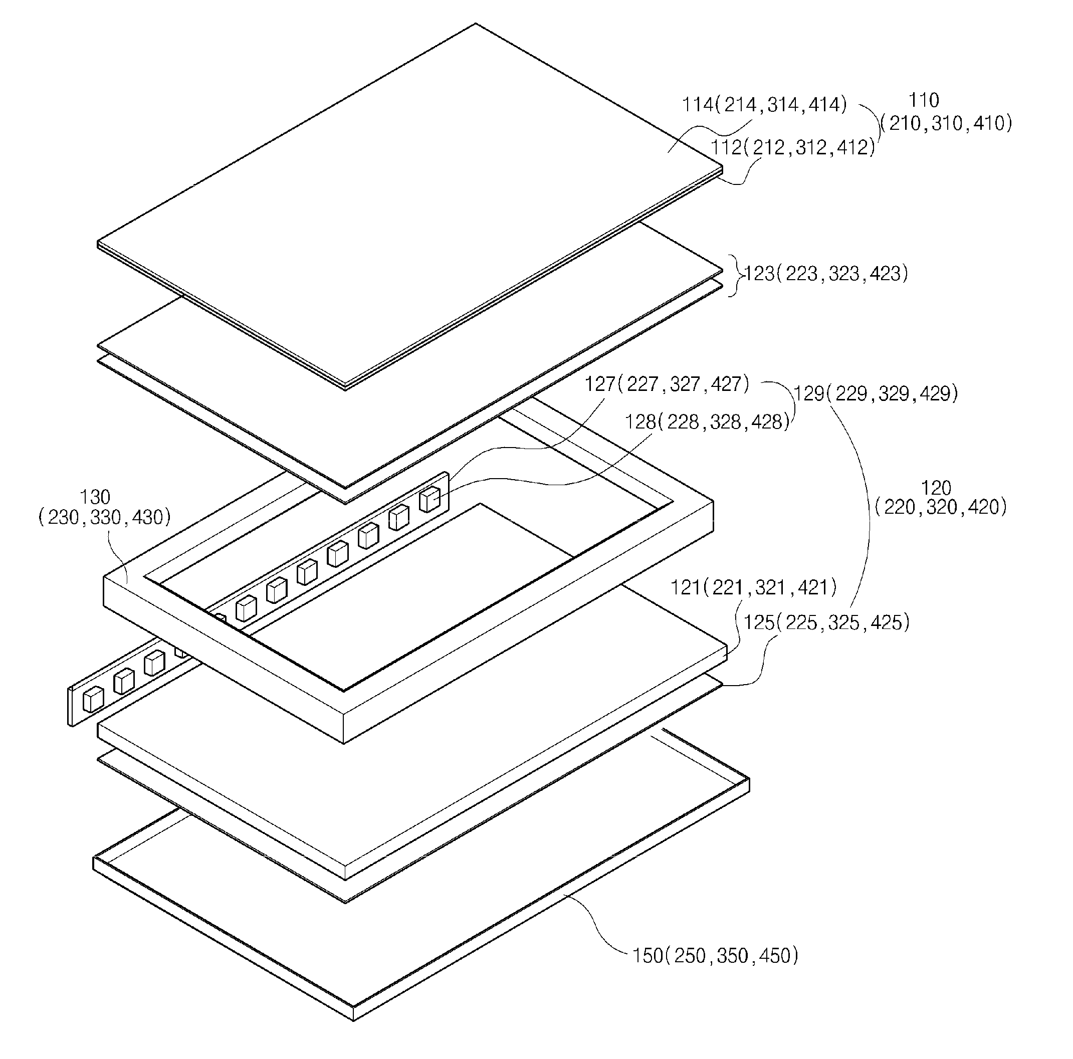
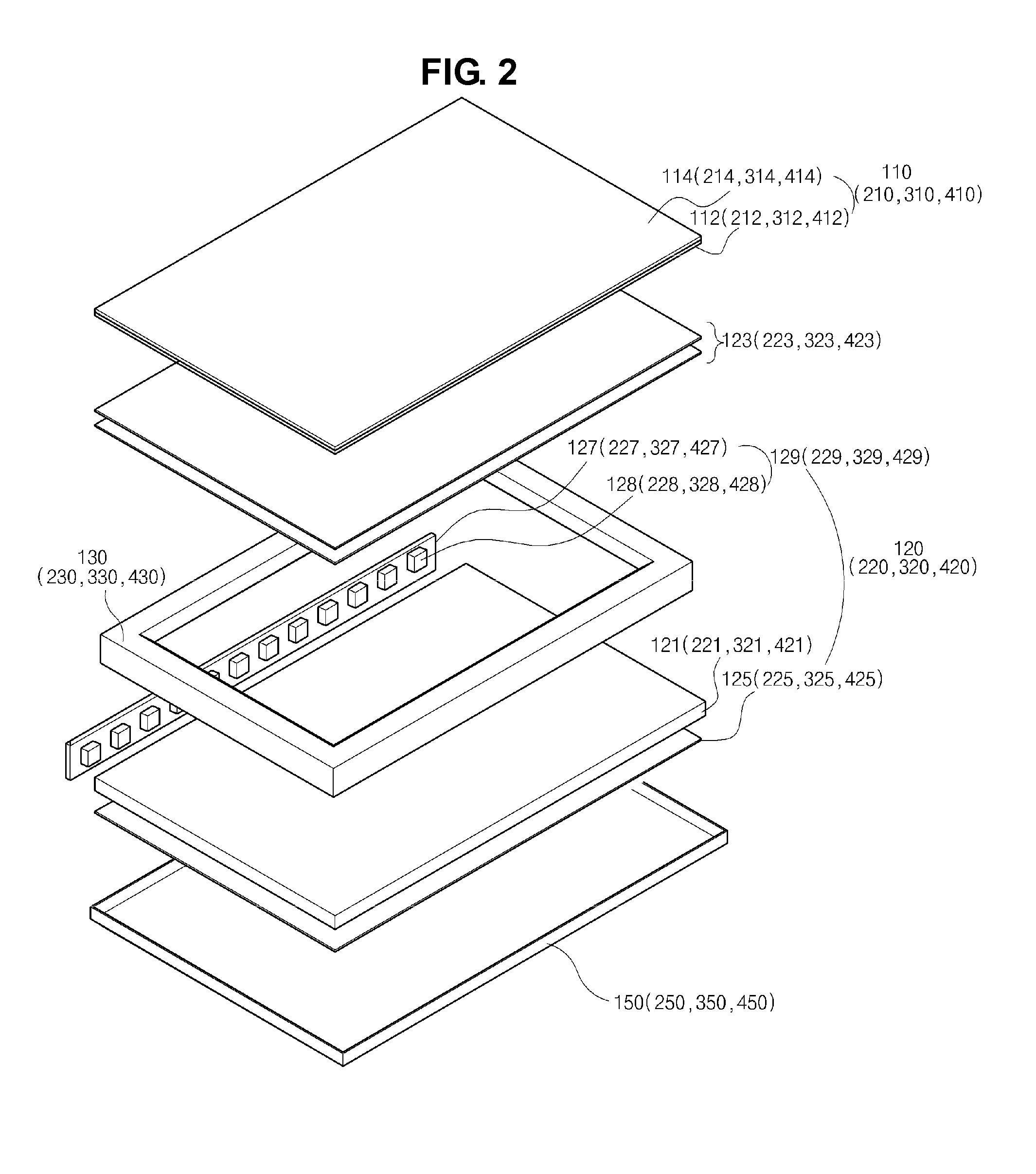
[0062]As shown in FIG. 3A, an LCD device includes a liquid crystal panel 110, a backlight unit 120, a main frame 130 and a bottom frame 150.

[0063]The liquid crystal panel 110 includes a first substrate 112, a second substrate 114 and a liquid crystal layer (not shown). The first substrate 112 and the second substrate 114 face each other, and the liquid crystal layer is interposed therebetween. The liquid crystal panel 110 has a plane area being substantially the same as a plane area of an outer dimension of the main frame 130.

[0064]The backlight unit 120 is disposed under the liquid crystal panel 110 and provides light onto the liquid crystal panel 110. The LCD device displays images using the light and a transmittance difference resulting from an operation of the liquid crystal layer.

[0065]The backlight unit 120 includes a light guide plate 121, a reflective s...

second embodiment

[0085]Referring to FIG. 4, which is a schematic cross-sectional view of an LCD device according to the present invention, the main frame 230 includes a first portion 232 being perpendicular to the liquid crystal panel 210 and a second portion 234 extending from the first portion 232 to be inclined toward the light guide plate 221.

[0086]Namely, in comparison to the main frame in FIG. 3A, the second portion 234 of the main frame 230 is directly extended from the first portion 232 without the third potion 136 (of FIG. 3A).

[0087]In the LCD device in FIG. 4, the first portion 232 of the main frame 230 surrounds the side of the backlight unit 220, and the second portion 234 of the main frame 130 covers the upper side of the LED assembly 229 and the front edge of the light guide plate 221. In addition, the liquid crystal panel 210 is supported by an end of the first portion 232 of the main frame 230.

[0088]As mentioned above, the light passing through an edge of a light-incident portion of ...

third embodiment

[0089]Referring to FIG. 5, which is a schematic cross-sectional view of an LCD device according to the present invention, the main frame 330 includes a first portion 332, which includes a first vertical portion 332a and a second vertical portion 332b, a second portion 334 extending downward direction with respect to the first portion 332 and a third portion 336 connecting the first and second portions 332 and 334 and being parallel to the liquid crystal panel 310.

[0090]In this instance, the first vertical portion 332a surrounds the side of the backlight unit 320, and a side of the liquid crystal panel 310 is supported by the second vertical portion 332b.

[0091]In addition, an optical sheet 323 may be disposed between the liquid crystal panel 310 and the third portion 336 of the main frame 330.

[0092]In the LCD device in FIG. 5, since the second vertical portion 332b surrounds the side of the liquid crystal panel 310, unnecessary motions of the liquid crystal panel 310 is prevented an...


PUM

PropertyMeasurementUnit
light transparencyaaaaaaaaaa
areaaaaaaaaaaa
adhesionaaaaaaaaaa

Abstract

A liquid crystal display device includes a liquid crystal panel; a backlight unit disposed under the liquid crystal panel and including a light guide plate and a light emitting diode (LED) assembly at a side of the light guide plate; a main frame surrounding a side of the backlight unit and having a light-diffusion property.

Description

[0001]The present application claims the benefit of Korean Patent Application Nos. 10-2012-0107401 and 10-2012-0136978 filed in Korea on Sep. 26, 2012 and Nov. 29, 2012, respectively, all of which are hereby incorporated by reference.BACKGROUND OF THE INVENTION[0002]1. Field of the Invention The present invention relates to a liquid crystal display (LCD) device and more particularly to an LCD device having an improved image-display region.[0003]2. Discussion of the Related Art[0004]The LCD device, which uses optical anisotropy and polarization properties to display an image, is widely used for notebook computers, monitors, TV, and so on, because of its high contrast ratio and characteristics adequate to display moving images.[0005]The LCD device includes a liquid crystal panel having a first substrate, a second substrate and a liquid crystal layer. The first and second substrates face each other, and the liquid crystal layer is interposed therebetween. An arrangement of the liquid c...

Claims


Application Information

Patent Timeline
Patent Type & Authority Applications(United States)
IPC IPC(8): G02F1/1335
CPCG02F1/133606G02F1/13336G02F1/133615G02F1/133317
Inventor CHOI, EUN-HEEPARK, JIN-SEO
Owner LG DISPLAY CO LTD
Why Eureka
Try Eureka