Bracket for correcting dentognathic deformity

Inactive Publication Date: 2014-04-17
LU HAIPING
View PDF3 Cites 0 Cited by
  • Summary
  • Abstract
  • Description
  • Claims
  • Application Information

AI Technical Summary

Benefits of technology

The present invention provides a bracket body and an accessory that can reduce friction force between the arch wire and the bracket, and adjust different correction effects through different parts. The bracket has a ligature wire loc groove and a ligature hole vertical to the direction of the arch wire groove, allowing for different methods of ligitation and adjusting friction force between the arch wire and bracket and between the arch wire and ligature wire according to demands. The movable lock can be easily inserted and removed, reducing operation time.

Problems solved by technology

In the traditional ligation method, the friction force between an arch wire and the bracket is relatively large, affecting the movement of teeth.
The self-locking bracket reduces the friction force between the arch wire and the bracket to a certain extent, but the self-locking bracket is complicated in structure and expensive in manufacturing.
Besides, a locking plate of the self-locking bracket and the arch wire are in surface contact and in strong friction when stressed.
More importantly, the self-locking bracket is unable to precisely control the locations of the teeth.

Method used


Image

  • Bracket for correcting dentognathic deformity
  • Bracket for correcting dentognathic deformity
  • Bracket for correcting dentognathic deformity

Examples


Embodiment Construction

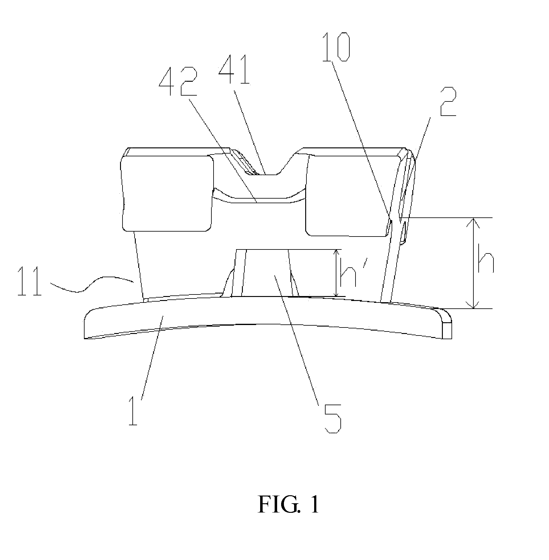
[0032]A bracket for correcting dentognathic deformity in the present invention can be used as a labial bracket or a lingual bracket.

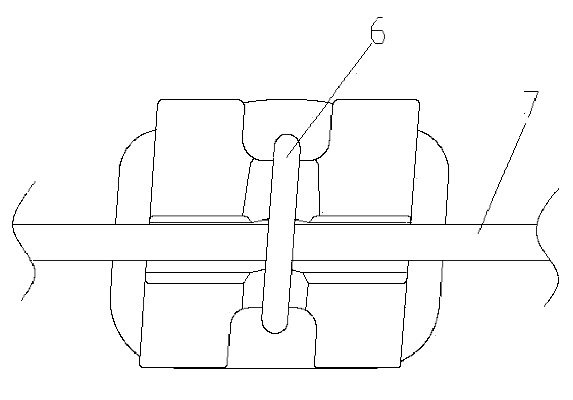
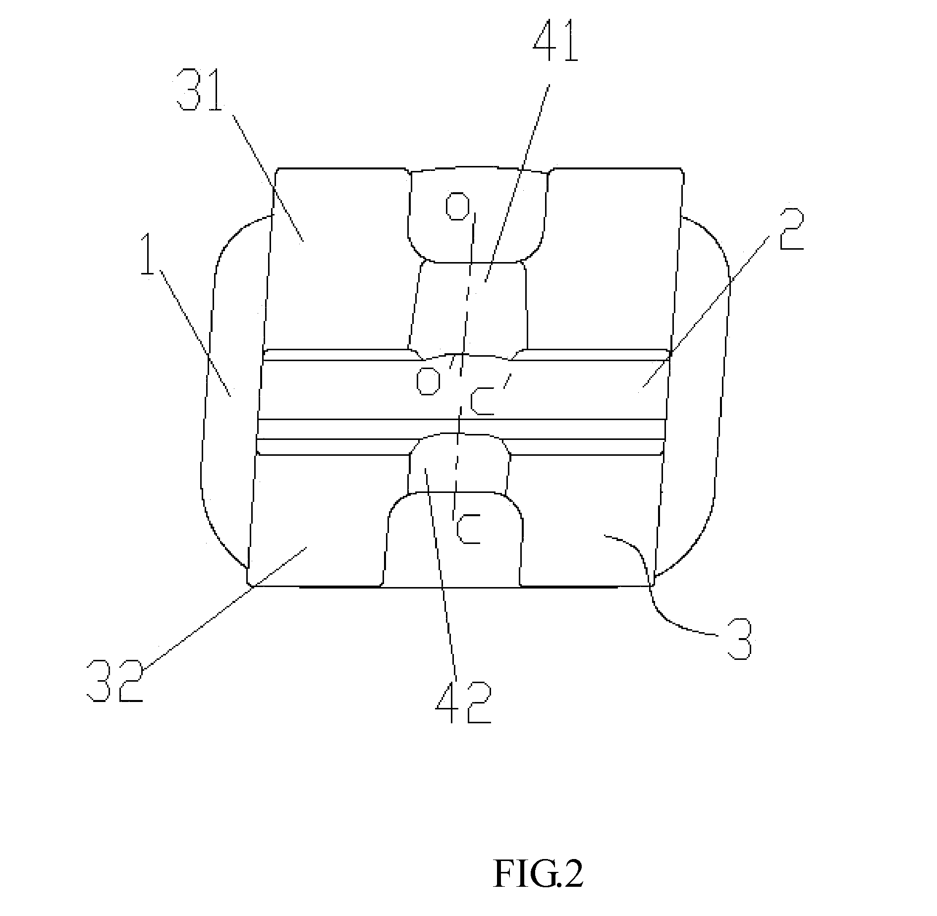
[0033]As shown in FIG. 1 and FIG. 2, the labial bracket for correcting dentognathic deformity of the present invention includes a substrate plate 1, a bracket body 11, and two working wings 31, 32. The bracket body 11 has an arch wire groove 2, and the working wing 31 and the working wing 32 are located at two sides of the arch wire groove 2. A lower part of the working wings 31, 32 has a ligature wire locating trench 10. The working wing 31 has a ligature wire locating groove 41, and the working wing 32 has a ligature wire locating groove 42. The groove bottom central line oo′ of the ligature wire locating groove 41 and the groove bottom central line cc′ of the ligature wire locating groove 42 are located on a same straight line. The same straight line is vertical to the arch wire groove 2. Certainly, in actual use, the same straight line may be at a c...


PUM


Abstract

This invention discloses a bracket for correcting dentognathic deformity including a substrate plate, a bracket body, and two working wings. The bracket body has an arch wire groove, and the working wings are located at two sides of the arch wire groove. The working wings have a ligature wire locating trench, and each wing has a ligature wire locating groove, groove bottom central lines of the ligature wire locating grooves are located on a same straight line. The bracket body has a ligature hole vertical to the arch wire groove and penetrating through the bracket body, and a vertical distance from a bottom surface of the arch wire groove to an upper surface of the substrate plate is larger than a height of the ligature hole. The bracket further has a C-shaped movable lock accessory. The placement and removement of the movable lock is convenient, greatly reducing the operation time.

Description

CROSS-REFERENCE TO RELATED APPLICATIONS[0001]This Non-provisional application is a Continuation-in-Part of U.S. patent application Ser. No. 13 / 952677 filed on Jul. 29, 2013, which claims priority under 35 U.S.C. §119(a) on Patent Application No(s). 201210391827.0 filed in People's Republic of China on Oct. 16, 2012, the entire contents of which are hereby incorporated by reference.BACKGROUND OF THE INVENTION[0002]1. Field of the Invention[0003]The present invention belongs to the field of dental orthodontics and, more particularly, to a bracket for correcting dentognathic deformity.[0004]2. Description of the Related Art[0005]A bracket for correcting dentognathic deformity is an important component used in the correction of dentognathic deformity of a patient. In the traditional ligation method, the friction force between an arch wire and the bracket is relatively large, affecting the movement of teeth. To improve the above mentioned situation, a self-locking bracket has been develo...

Claims


Application Information

Patent Timeline
IPC IPC(8): A61C7/30
CPCA61C7/30A61C7/28A61C7/287
Inventor LU, HAIPING
Owner LU HAIPING
Why Eureka
Try Eureka