Fast start induction RF fluorescent light bulb

a fluorescent light bulb and induction rf technology, applied in the direction of discharge tube/lamp details, energy-saving lighting, sustainable buildings, etc., can solve the problems of long lamp structure, inability to replace conventional incandescent lamps, and inability to meet the needs of use, so as to reduce power consumption and noise, the effect of reducing the flicker of the lamp

Active Publication Date: 2014-05-29
LUCIDITY LIGHTS
View PDF8 Cites 29 Cited by
  • Summary
  • Abstract
  • Description
  • Claims
  • Application Information

AI Technical Summary

Benefits of technology

[0027]In embodiments, the induction RF fluorescent lamp may comprise a dimming device load control facility enabling the induction RF fluorescent lamp to provide for electrical loads required for the proper operation of an external control dimming device, the dimming device load control facility controlling a switched electrical load switched in and out of connectivity within the electronic ballast to provide a load for the external dimming device. The dimming device load control facility may detect an external dimming device type for the external dimming control device and automatically adjust the control of the switched electrical load based on the detected device type, such as a leading-edge type external dimming device, a trailing-edge type external dimming device, a smart type external dimming device, a

Problems solved by technology

Use of electrodes can create certain problems.
In the case of fluorescent lamps, this may lead to long, thin lamp structures, which function well for lighting office ceilings, but are not always a good fit for replacing conventional incandescent lamps.
A plastic cover shaped like a conventional incandescent lamp is sometimes placed over the bent tubes to provide a more attractive shape, but these covers absorb light, making the lamp less efficient.
Bent and spiral tube lamps also have wasted space between the tubes, making them larger than necessary.
The use of electrodes can create problems other than shape and size.
Electrodes can wear out if the lamp is turned on and off many times, as is typical in a residential bathroom and many other applications.
In addition, the long thin shape se

Method used


Image

  • Fast start induction RF fluorescent light bulb
  • Fast start induction RF fluorescent light bulb
  • Fast start induction RF fluorescent light bulb

Examples


Embodiment Construction

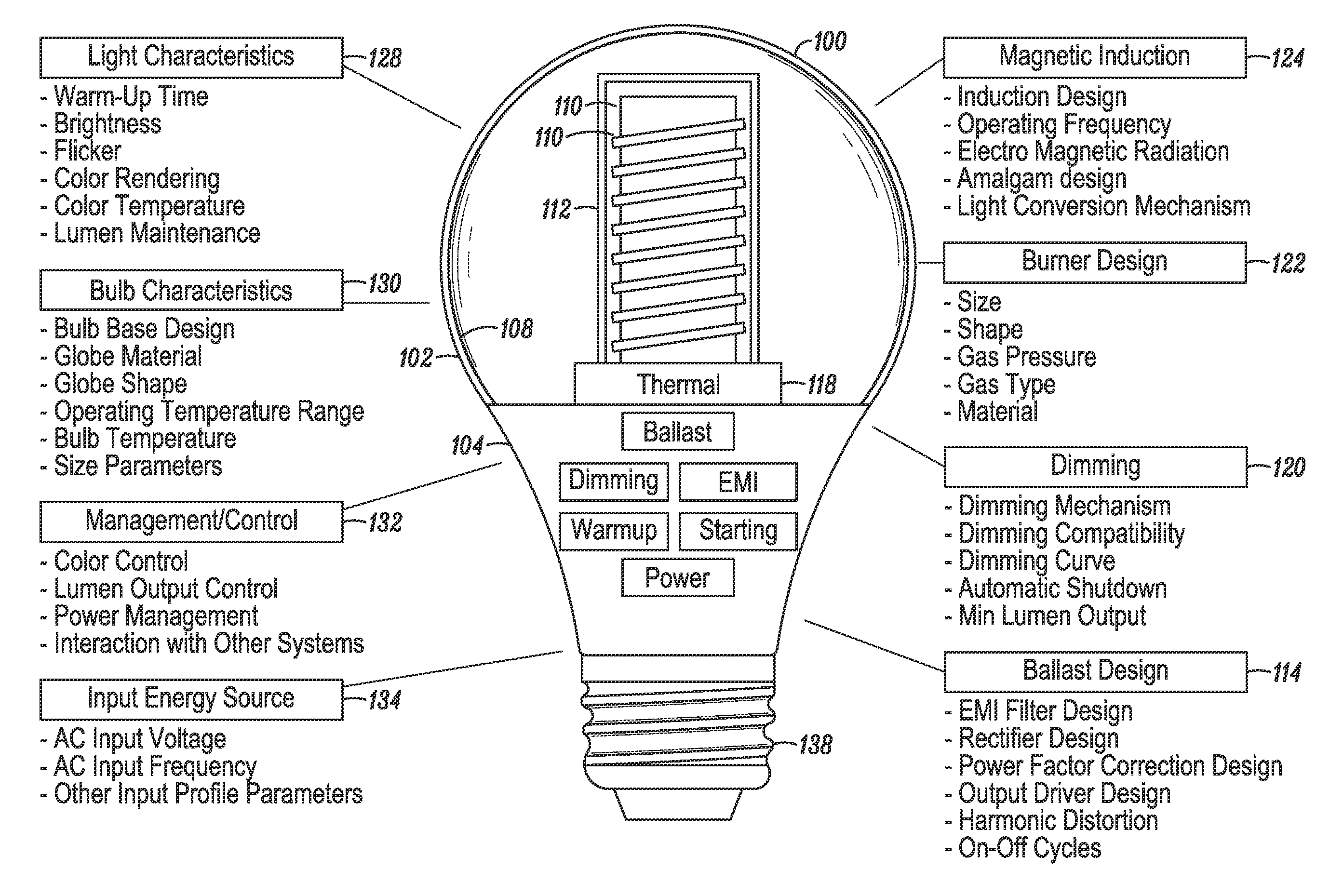
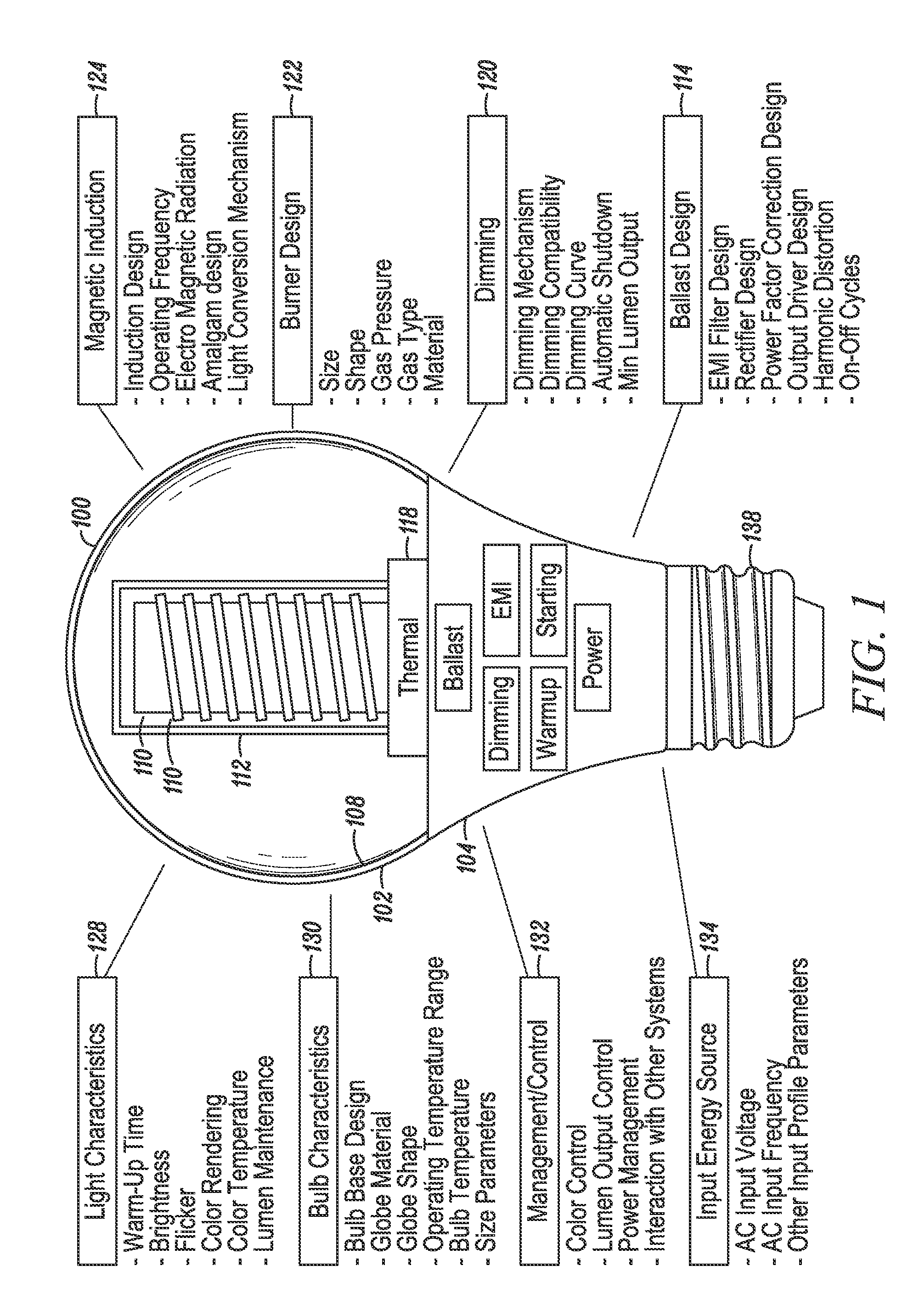
[0064]An induction-driven electrodeless discharge lamp, hereafter referred to synonymously as an induction lamp, an electrodeless lamp, or an electrodeless fluorescent lamp, excites a gas within a lamp envelope through an electric field created by a time-varying magnetic field rather than through electrically conductive connections (such as electrodes) that physically protrude into the envelope. Since the electrodes are a limiting factor in the life of a lamp, eliminating them potentially extends the life that may be expected from the light source. In addition, because there are no metallic electrodes within the envelope, the burner design may employ high efficiency materials that would otherwise react with the electrodes, such as bromine, chlorine, iodine, and the like, and mixtures thereof, such as sodium iodide and cerium chloride. Embodiments described herein disclose an inductor mounted inside a re-entrant cavity protruding upward within the burner envelope, where the inductor ...


PUM


Abstract

A fast starting induction RF fluorescent lamp that is able to replace an ordinary incandescent light bulb, both in its ability to screw into a standard incandescent light bulb socket and to have the general look of the ordinary incandescent light bulb, but with all of the advantages of an induction lamp, as described herein. The present disclosure describes structures for an induction RF fluorescent lamp that includes a bulbous portion, an electronics portion, and a screw base, creating an external look that is similar to the profile of an ordinary incandescent light bulb, and with structures within the bulbous portion that facilitate rapid luminous development during the turn-on phase of the induction fluorescent lamp.

Description

CROSS-REFERENCE TO RELATED APPLICATIONS[0001]This application is a continuation-in-part of the following U.S. patent application, which is hereby incorporated by reference in its entirety: U.S. patent application Ser. No. 14 / 030,758, filed Sep. 18, 2013.[0002]The application Ser. No. 14 / 030,758 is a continuation-in-part of the following U.S. patent application, which is hereby incorporated by reference in its entirety: U.S. patent application Ser. No. 14 / 016,363, filed Sep. 3, 2013.[0003]The application Ser. No. 14 / 016,363 is a continuation-in-part of the following U.S. patent application, which is hereby incorporated by reference in its entirety: U.S. patent application Ser. No. 13 / 968,766, filed Aug. 16, 2013.[0004]The application Ser. No. 13 / 968,766 is a continuation-in-part of the following U.S. patent application, which is hereby incorporated by reference in its entirety: U.S. patent application Ser. No. 13 / 957,846, filed Aug. 2, 2013.[0005]The application Ser. No. 13 / 957,846 i...

Claims


Application Information

Patent Timeline
IPC IPC(8): H01J1/52
CPCH01J65/048H05B41/2806H05B41/3921Y02B20/00
Inventor GOSCHA, JOHN R.LAPATOVICH, WALTER PETERGOODMAN, DAVID ALANWENTZEL, DAVID
Owner LUCIDITY LIGHTS
Why Eureka
Try Eureka