Display device

Active Publication Date: 2014-07-24
SAMSUNG DISPLAY CO LTD
View PDF12 Cites 11 Cited by
  • Summary
  • Abstract
  • Description
  • Claims
  • Application Information

AI Technical Summary

Benefits of technology

[0020]According to the above, a display device may have high stress resistance to protect the display device

Problems solved by technology

As a result, a display device manufacturin

Method used


Image

  • Display device
  • Display device
  • Display device

Examples


Embodiment Construction

[0035]It will be understood that when an element or layer is referred to as being “on”, “connected to” or “coupled to” another element or layer, it can be directly on, connected or coupled to the other element or layer or intervening elements or layers may be present. Like numbers refer to like elements throughout.

[0036]Hereinafter, exemplary embodiments of the present disclosure will be explained in detail with reference to the accompanying drawings.

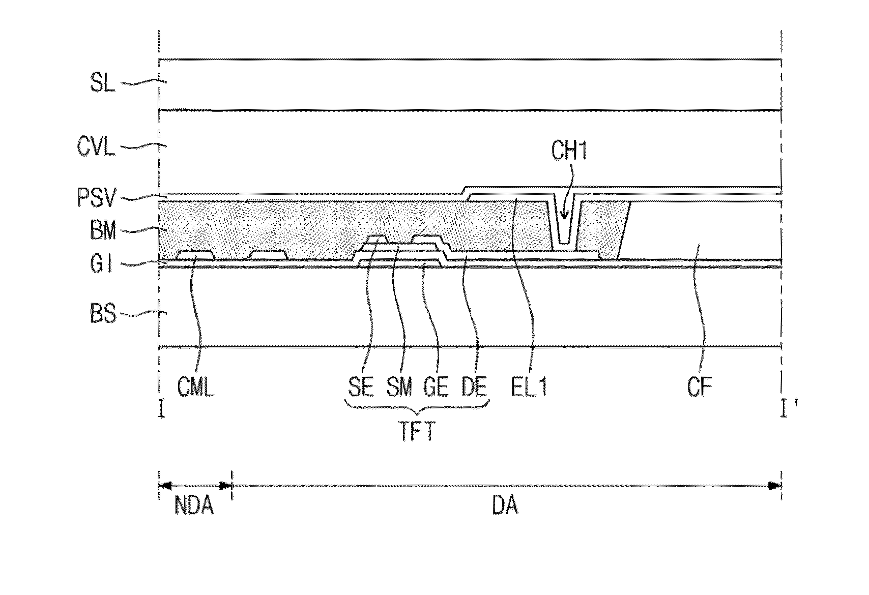
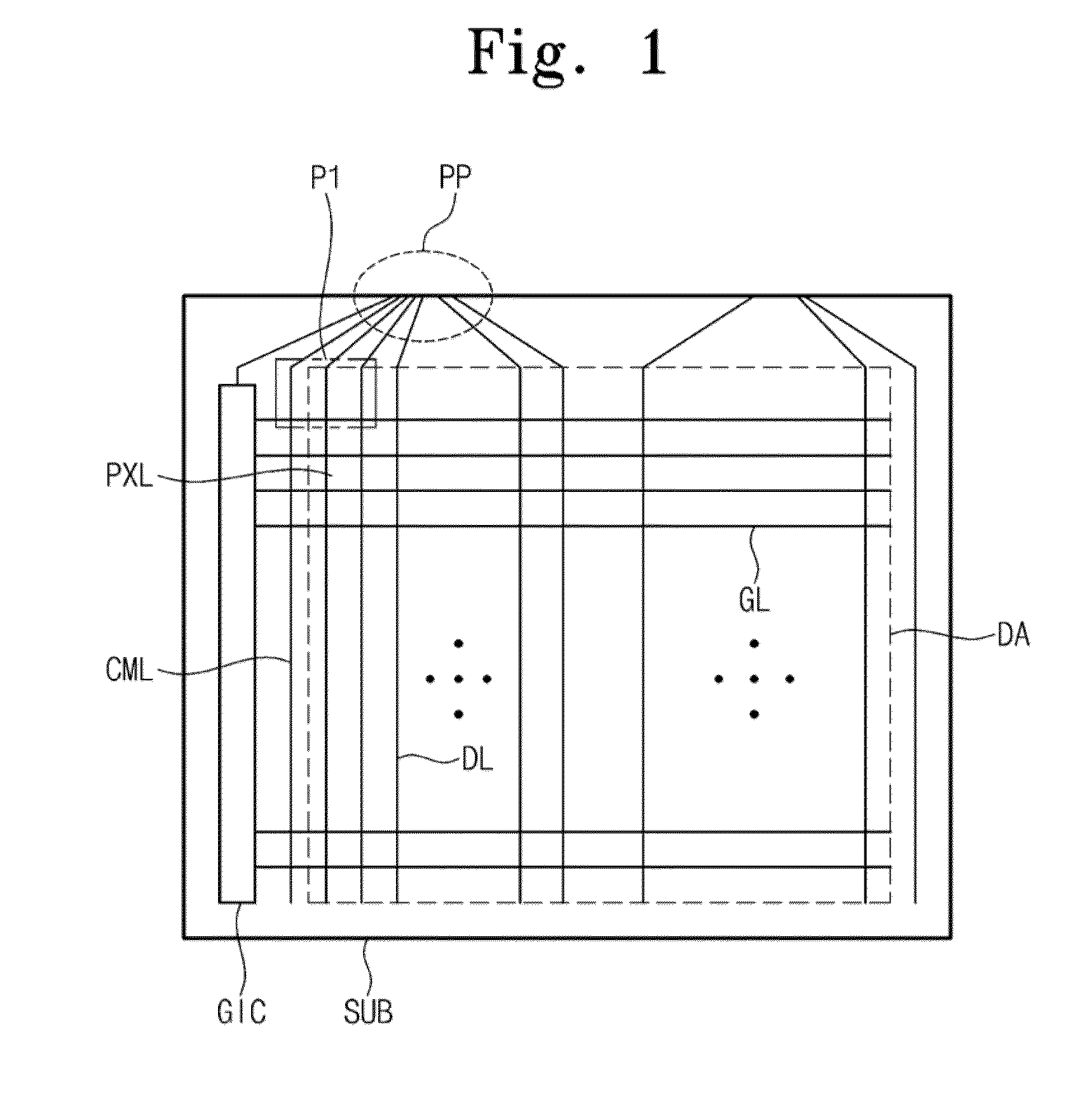
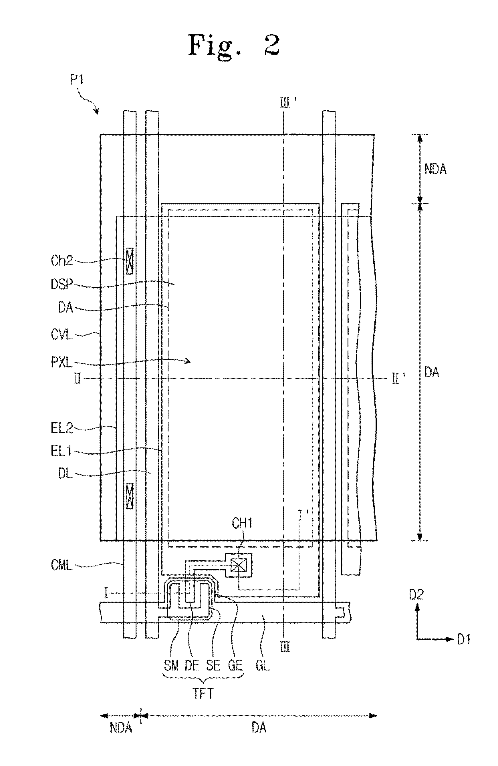
[0037]FIG. 1 is a plan view of a display device according to an exemplary embodiment of the present disclosure and FIG. 2 is a plan view of a portion of the display device shown in FIG. 1. FIG. 3A is a cross-sectional view taken along a line I-I′ shown in FIG. 2, FIG. 313 is a cross-sectional view taken along a line II-II′ shown in FIG. 2, and FIG. 3C is a cross-sectional view taken along a line III-III′ shown in FIG. 2.

[0038]The display device shown in FIG. 1 includes a plurality of pixels PXL arranged in a matrix form with a plurality...


PUM


Abstract

A display device includes a substrate and pixels arranged on the substrate in a matrix form. The substrate includes a display area in which the pixels are arranged and a non-display area disposed adjacent to a side of the display area. Each pixel includes a cover layer that extends in a row direction that includes a sidewall portion connected to the substrate and a cover portion spaced apart from the substrate and connected to the sidewall portion to define a tunnel-shaped cavity on the substrate. A width of the sidewall portion between adjacent pixels is less than a width of the sidewall portion disposed at an outermost position, and the cover layer seals one side of the tunnel-shaped cavity in the pixels arranged in a first row and a last row.

Description

CROSS-REFERENCE TO RELATED APPLICATION[0001]This U.S. non-provisional patent application claims priority under 35 U.S.C. §119 from Korean Patent Application No. 10-2013-0007572, filed on Jan. 23, 2013 in the Korean Intellectual Property Office, the contents of which are herein incorporated by reference in their entirety.BACKGROUND[0002]1. Technical Field[0003]The present disclosure relates to a display device.[0004]2. Discussion of the Related Art[0005]In recent years, flat screen display devices such as liquid crystal display devices, electrophoretic display devices, etc., have become more widely used instead of cathode ray tubes.[0006]A display device includes two substrates facing each other and an image display unit interposed between the two substrates, such as a liquid crystal layer, an electrophoretic layer, etc. The two substrates are coupled to each other while facing each other and spaced apart from each other by a distance that allows the image display unit to be disposed...

Claims


Application Information

Patent Timeline
IPC IPC(8): H01L33/08G02F1/1681
CPCG02F1/167G02F1/133377G02F1/1681H01L27/1214H01L27/124G09G3/3607G09G3/3655G09G2310/027H04N9/30
Inventor KIM, YEUN-TAELEE, HEE-KEUNLIM, JAEKEUN
Owner SAMSUNG DISPLAY CO LTD
Why Eureka
Try Eureka