Vascular plug

a technology of vascular plugs and occluders, applied in the field of vascular plugs or occluders, can solve the problems of loss of positional orientation, inability to produce immediate occlusion of the vessel, and insufficient thrombosis that can take hours, days or even weeks, and achieve the effect of promoting thrombosis

a technology of vascular plugs and occluders, applied in the field of vascular plugs or occluders, can solve the problems of loss of positional orientation, inability to produce immediate occlusion of the vessel, and insufficient thrombosis that can take hours, days or even weeks, and achieve the effect of promoting thrombosis

US20140207172A1Active Publication Date: 2014-07-24COOK MEDICAL TECH LLC

Image

  • Vascular plug
  • Vascular plug
  • Vascular plug

Examples


Embodiment Construction

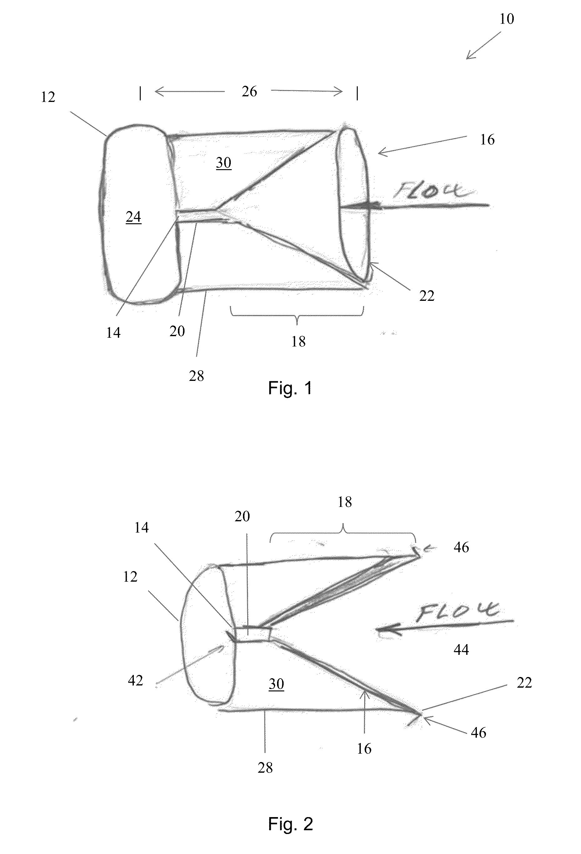
[0036]Referring to FIG. 1, there is shown a first embodiment of plug 10 according to the present invention. The view shown is a side elevational view in partial cross-section. The plug includes an inflatable element 12 which could be described as a balloon, which may be made of conventional balloon material such as polyurethane, polyamide such as Nylon, polyether block amide such as Pebax, or any other suitable material. In the preferred embodiment, the material of the inflatable element 12 is an expandable or elastic material such as silicone or a thermoplastic elastomer.

[0037]The inflatable element 12 is in transverse cross-section, in practice perpendicular to the vessel and direction of fluid flow as shown by the arrow in FIG. 1, generally circular so as to have a shape consistent with the cross-sectional shape of the vessel. The inflatable member element 12 may have a transverse diameter, normal to the direction of flow, which is greater than its length, as can be seen in FIG. ...


PUM


Abstract

A vascular plug for implantation into a patient's vessel includes an inflatable balloon and a flow accelerator. The flow accelerator includes a conical portion and a tubular coupling element which couples the conical portion to an aperture to the interior of the inflatable balloon. The flow accelerator will concentrate and therefore accelerate fluid flow into the inflatable balloon. Flow accelerator will increase the pressure of fluid thereby to cause the inflatable balloon to inflate even within a pressurised blood vessel. The plug may include a sleeve which provides a chamber between the flow accelerator and the balloon, into which blood may pass from the inflatable balloon or the flow accelerator to create additional blood statis and as a result thrombosis and a second occlusive barrier.

Description

CROSS-REFERENCE TO RELATED APPLICATIONS[0001]This application is related to and claims the benefit of priority to GB 1300930.3, filed on Jan. 18, 2013 which is incorporated herein by reference in its entirety.TECHNICAL FIELD[0002]The present invention relates to a vascular plug or occluder for closing a body vessel.BACKGROUND ART[0003]Vascular occluders have been known for a number of years. Many types are in the form of a device which is implanted within a vessel of the patient and which has a structure which closes off the vessel so as to occlude blood flow. Occluders of this nature, sometimes referred to as vascular plugs, are preferable over more traditional forms of occluder, such as vascular constrictors, which generally require an invasive medical procedure. Vascular occluders, on the other hand, can be deployed endoluminally in a significantly faster and less traumatic medical procedure.[0004]Vascular occluders may be designed or used to provide temporary occlusion, for exam...

Claims


Application Information

Patent Timeline
24 Jul 2014
Publication
US20140207172A1
IPC
A61B17/12
CPC
A61B17/12109; A61B17/12136
Inventors
BODEWADT, TUE THUREN; HANSEN, CHRISTINA RAUFF