Blast attenuation seat

a technology of attenuation seat and seat, which is applied in the field of seats, can solve the problems of injuring the occupant, injuring the occupant, and vehicles can be exposed to blasts, and achieve the effect of simplifying the tuning of the energy absorption devi

Inactive Publication Date: 2014-08-07
SURVIVABILITY SOLUTIONS
View PDF28 Cites 16 Cited by
  • Summary
  • Abstract
  • Description
  • Claims
  • Application Information

AI Technical Summary

Benefits of technology

[0010]Since the link is pivotably coupled to the seat pan and the seat bottom frame and guides movement of the seat pan relative to the seat bottom frame, the relative movement of the seat pan and the seat bottom frame is repeatable. The repeatability of the relative movement of the seat pan and the seat bottom frame simplifies the tuning of the energy absorbing device to properly absorb at least a portion of the force between the occupant and the vehicle when the seat pan moves relative to the seat bottom frame.

Problems solved by technology

Such vehicles can be exposed to blasts resulting from an explosive such as an improvised explosive device, a mine, a grenade, etc.
The vibration and / or reverberation of the blast through the vehicle can injure the occupants.
This vibration and / or reverberation through the vehicle can injure the occupant.
In such a scenario, the occupant can be harmed if this vibration and / or reverberation is transferred directly to the occupant through the floor and / or the seat.
Further, whether the vehicle is armored or not, much of the technology for absorbing energy in a civilian automobile during an automobile accident is not suitable for absorbing energy from an explosive blast.
As such, the airbags used in civilian automobiles cannot react quickly enough due to the 5 millisecond delay associated with the civilian automobile airbags.
In addition to generating initial forces acting on the vehicle, the blast can also cause the vehicle to become airborne.
The occupant can suffer injuries relating to the landing of the vehicle on the ground, i.e., the “slam down.”

Method used


Image

  • Blast attenuation seat
  • Blast attenuation seat
  • Blast attenuation seat

Examples


Embodiment Construction

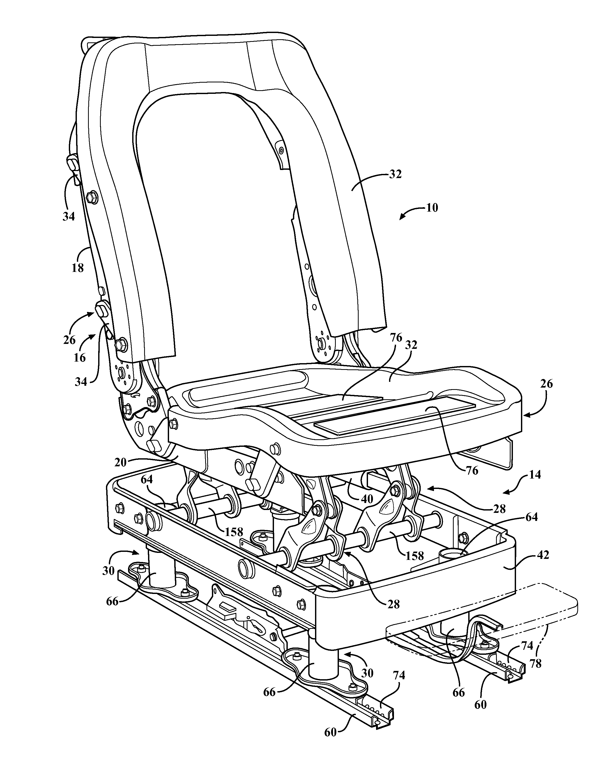
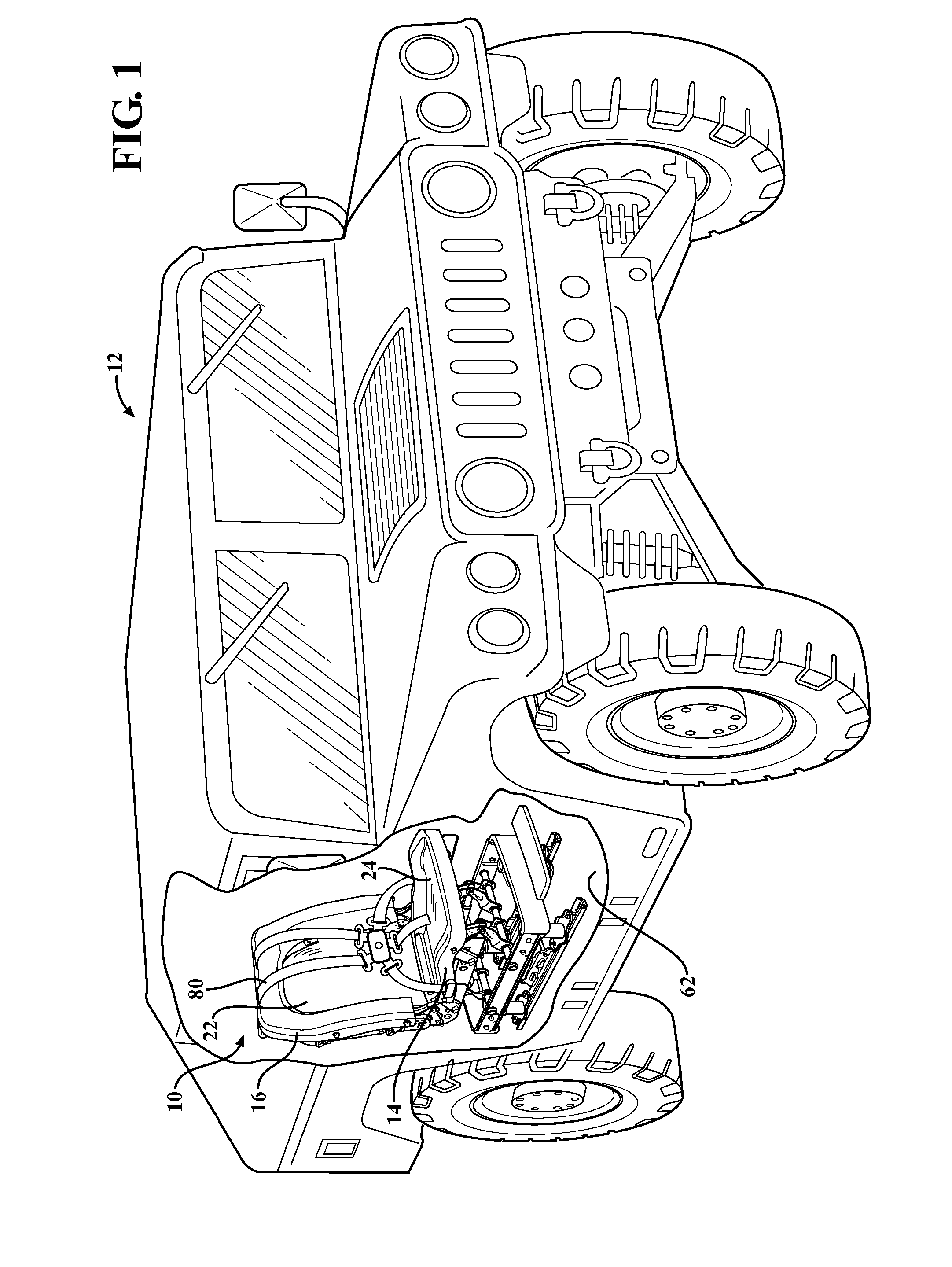
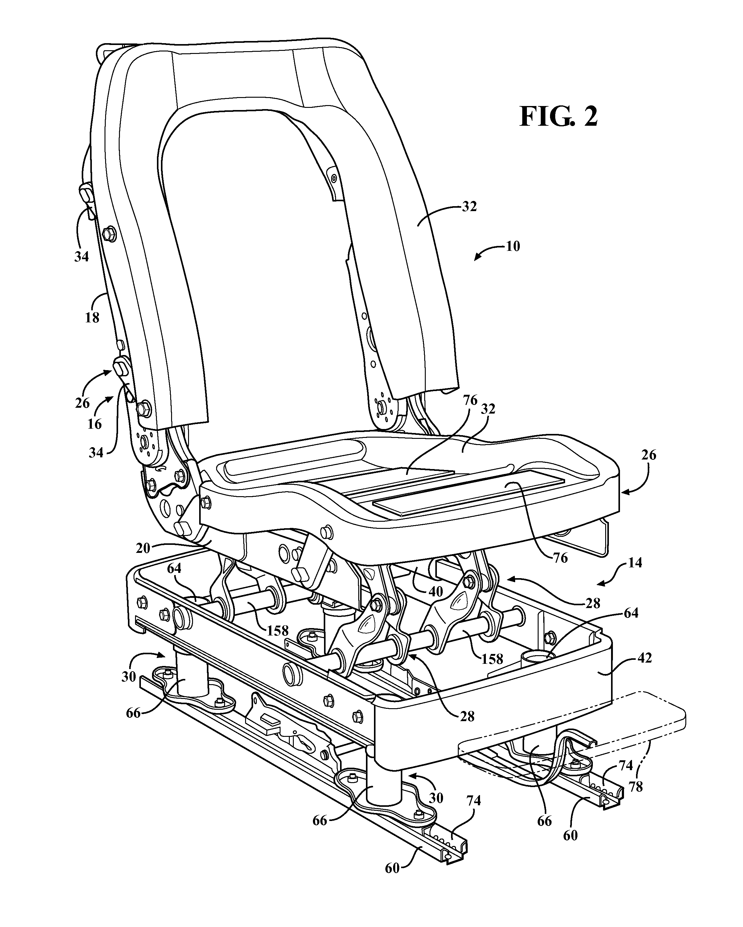
[0034]Referring to the Figures, wherein like numerals indicate like parts throughout the several views, a blast attenuation seat is shown generally at 10, 110, 210 and is referred to hereinafter as “the seat.” As shown in FIGS. 1 and 10, the seat 10, 210 is mounted in a vehicle 12 for supporting an occupant (shown in FIG. 13, for example). A first embodiment of the seat 10 is shown in FIGS. 1-8, a second embodiment of the seat 110 is shown in FIG. 9, and a third embodiment of the seat 210 is shown in FIGS. 10-16.

[0035]The seat 10 is typically mounted in a military vehicle but can also be mounted in a non-military vehicle such as, for example, a law enforcement vehicle or a civilian vehicle. Whether the vehicle 12 is a military vehicle or otherwise, the vehicle 12 can be a land vehicle such as, for example, an automobile, a tank, a bus, a train, etc.; a water vehicle such as, for example, a boat or a submarine; or an air vehicle such as, for example, an airplane or helicopter. Typica...


PUM


Abstract

A seat supports an occupant of a vehicle and absorbs a force between the occupant and the vehicle created by relative movement between the occupant and the vehicle. The seat includes a seat back and a seat bottom frame supporting the seat back and extending from the seat back along an axis. A seat pan is moveably coupled to the seat bottom frame and an energy absorbing device is coupled to the seat bottom frame and the seat pan. The energy absorbing device is configured to absorb at least a portion of the force between the occupant and the vehicle when the seat pan moves relative to the seat bottom frame. A link is pivotably coupled to the seat pan and to the seat bottom frame and guides movement of the seat pan relative to the seat bottom frame away from the seat back along the axis when the seat pan moves relative to the seat bottom frame.

Description

CROSS-REFERENCE TO RELATED APPLICATIONS[0001]The subject patent application is a continuation-in-part of U.S. patent application Ser. No. 13 / 077,423 filed on Mar. 31, 2011, which claims priority to and all the benefits of U.S. Provisional Patent Application No. 61 / 341,470 filed on Mar. 31, 2010, the entire specifications of which are expressly incorporated herein by reference. The subject application also claims priority to and all the benefits of U.S. Provisional Patent Application No. 61 / 797,105 filed on Nov. 29, 2012 and U.S. Provisional Patent Application No. 61 / 787,835 filed on Mar. 15, 2013, the entire specifications of which are expressly incorporated herein by reference.BACKGROUND OF THE INVENTION[0002]1. Field of the Invention[0003]The present invention relates to a seat for supporting an occupant of a vehicle and absorbing a force between the occupant and the vehicle created by relative movement between the occupant and the vehicle[0004]2. Description of the Related Art[00...

Claims


Application Information

Patent Timeline
Patent Type & Authority Applications(United States)
IPC IPC(8): F41H7/04
CPCF41H7/046B60N2/502B60N2/503B60N2/504B60N2/506B60N2/507B60N2/525B60N2/527B60N2/548B60N2/24B60N2/4242B60N2/42709B60N2/42736B60N2/546B60N2/688B60N2/885
Inventor LAMPARTER, RONALD C.COMAN, SORINMCLEOD, HUGH S.MESSNER, THOMAS
Owner SURVIVABILITY SOLUTIONS
Why Eureka
Try Eureka