

Needle protecting module of an injecting device and an injection device with a needle protecting module
a technology of injection device and protecting module, which is applied in the direction of intravenous device, infusion needle, other medical devices, etc., can solve the problems of inability to move smoothly the mounting tube b>18/b>, and the drawbacks of the conventional syringe b>1/b>, so as to facilitate a safe clinical injection practice
- Summary
- Abstract
- Description
- Claims
- Application Information
AI Technical Summary
Benefits of technology
Problems solved by technology
Method used
Image

Examples
Embodiment Construction
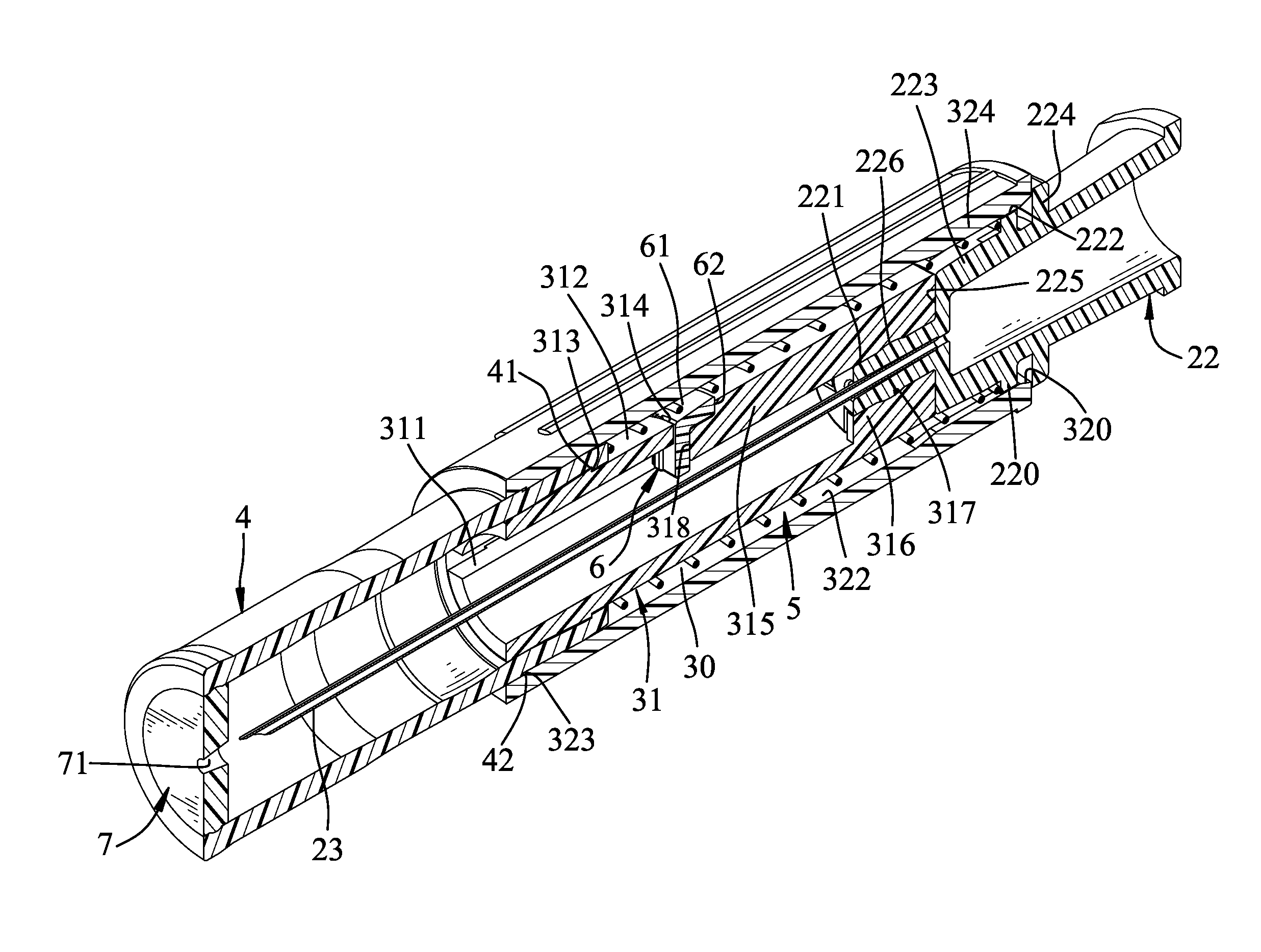
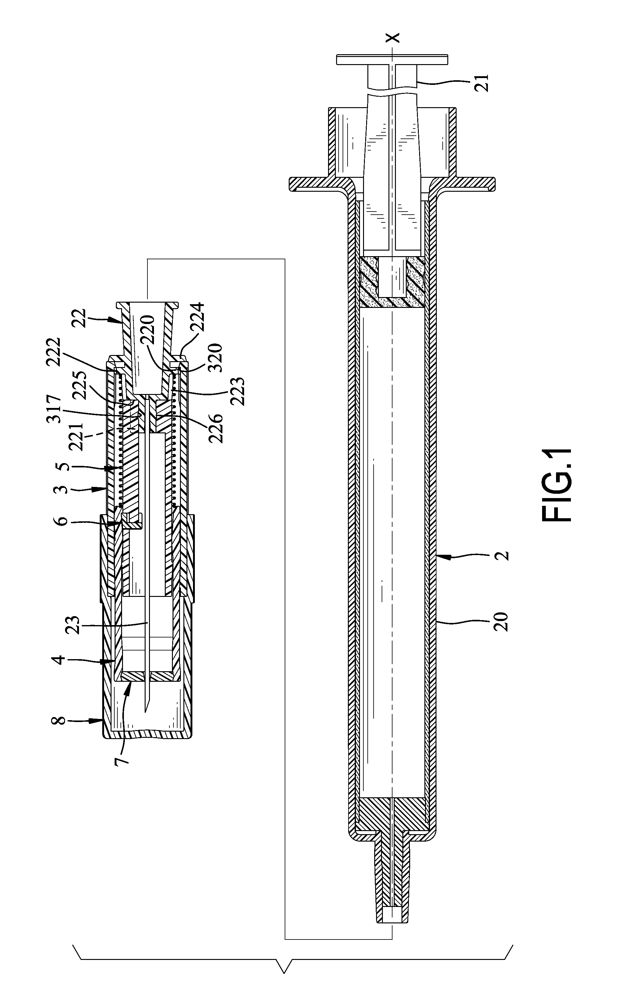
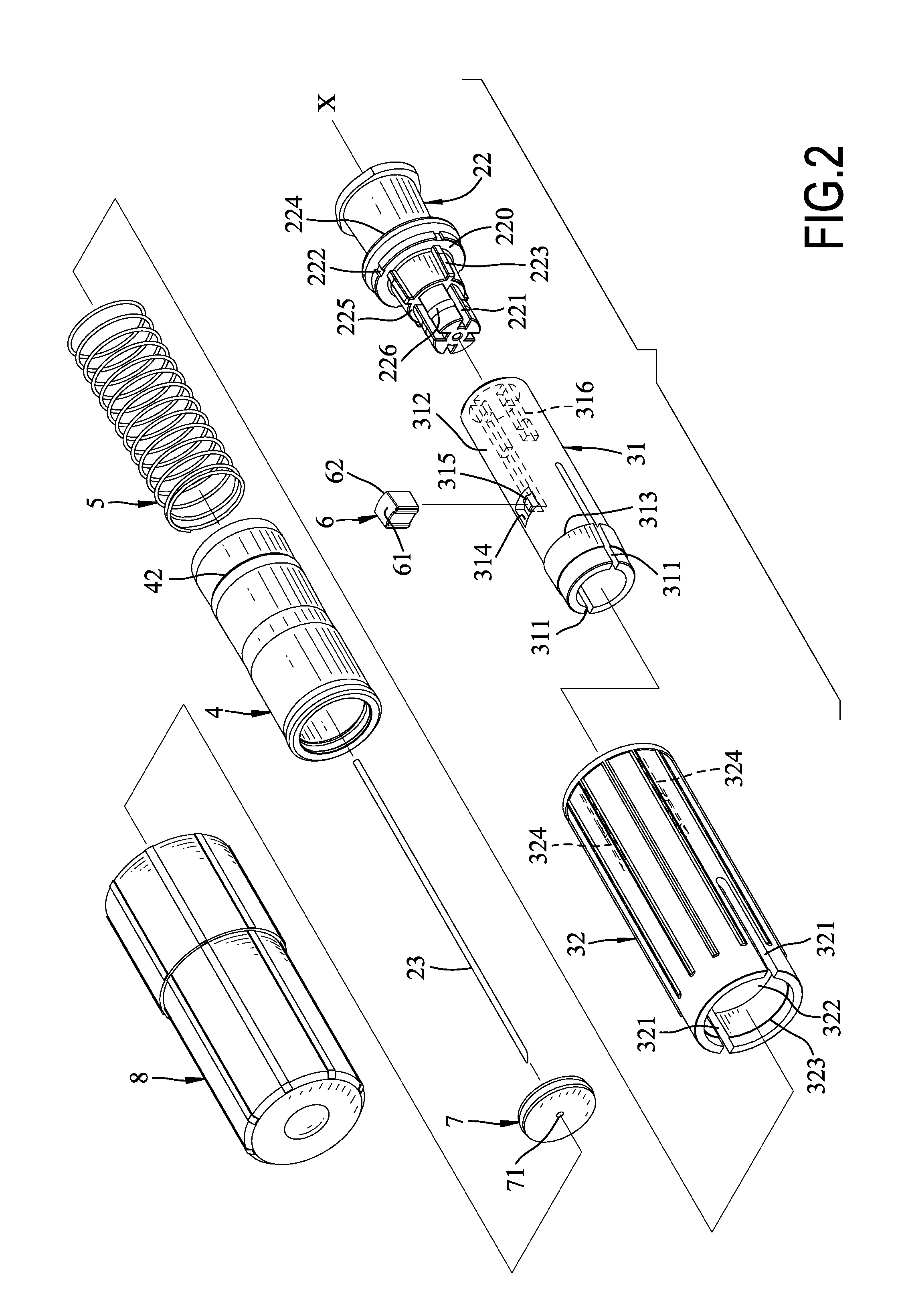
[0053]With reference to FIGS. 1 to 3, a first preferred embodiment of a needle protecting module of an injection device in accordance with the present invention comprises a needle base 22, a needle body 23, a tube module 3, a mounting tube 4, an elastic unit 5, a stopping unit 6, a cover 7, and a mounting cover 8.
[0054]With reference to FIGS. 1 and 4, the needle protecting module can be removably connected with an injection device, a syringe 2 for this example for a safe injection practice. The syringe 2 has a tube body 20, an axis X, and a pushing stick module 21. The pushing stick module 21 is slidably and airtightly mounted in the tube body 20 parallel with the axis X.
[0055]The needle body 23 in communication with the tube body 20 is parallel with the axis X and can penetrate out of the needle protecting module for medication injection
[0056]The needle base 22 is formed enabling to be removablely engaged with the tube body 20 and is transfixed by the needle body 23, and parallels ...
PUM
 Abstract
Description
Claims
Application Information