
wind turbine nacelle

A technology for wind turbines and nacelles, which is applied in wind turbines, wind power generation, engines, etc., can solve problems such as economic losses, difficulty in maintaining and replacing large parts and components, and dangers, so as to prevent rain leakage and be convenient, economical and practical. , to avoid the effect of unsafe operation

Active Publication Date: 2016-08-24
GUODIAN UNITED POWER TECH CHIFENG
View PDF8 Cites 0 Cited by
  • Summary
  • Abstract
  • Description
  • Claims
  • Application Information

AI Technical Summary

Problems solved by technology

The top opening of the existing wind turbine nacelle cover is small, which can only be used by maintenance personnel to enter and exit and replace small parts of the unit, but it involves the maintenance and replacement of large parts with high failure rates such as bearings, gearboxes, and generators. It is more difficult. It is necessary to remove the upper cover or hoist the whole machine to the ground for replacement, resulting in high maintenance costs, long periods, and great difficulty, which seriously affects the operation of the unit and causes huge economic losses.
Moreover, the current hole cover structure of the top opening of the wind turbine cabin cover is a sliding door structure, which needs to be manually pushed and pulled, which is dangerous to a certain extent.
Nowadays, the nacelle of offshore wind turbines is developing day by day, and it is more difficult to maintain and replace some large parts of offshore wind turbines.
[0003] It can be seen that the above-mentioned existing wind turbine nacelle cover top opening is small and the hole cover is a sliding door structure. In terms of structure, method and use, there are obviously still inconveniences and defects, and it is urgent to be further improved.

Method used


Image

  • wind turbine nacelle
  • wind turbine nacelle
  • wind turbine nacelle

Examples


Embodiment Construction

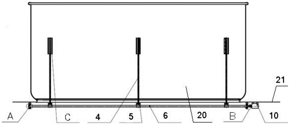
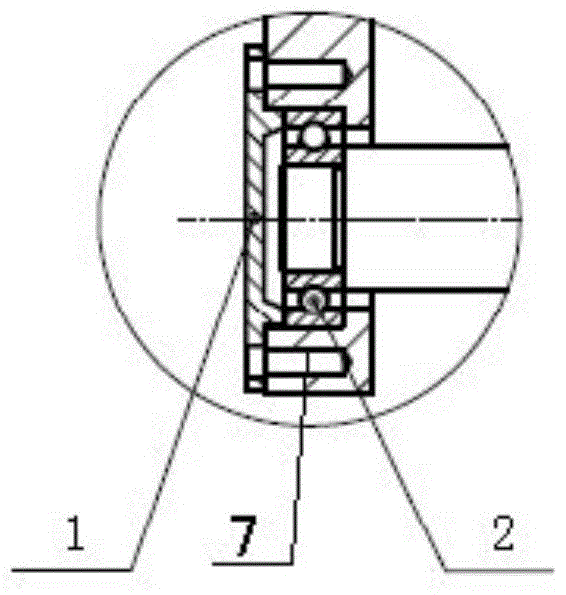
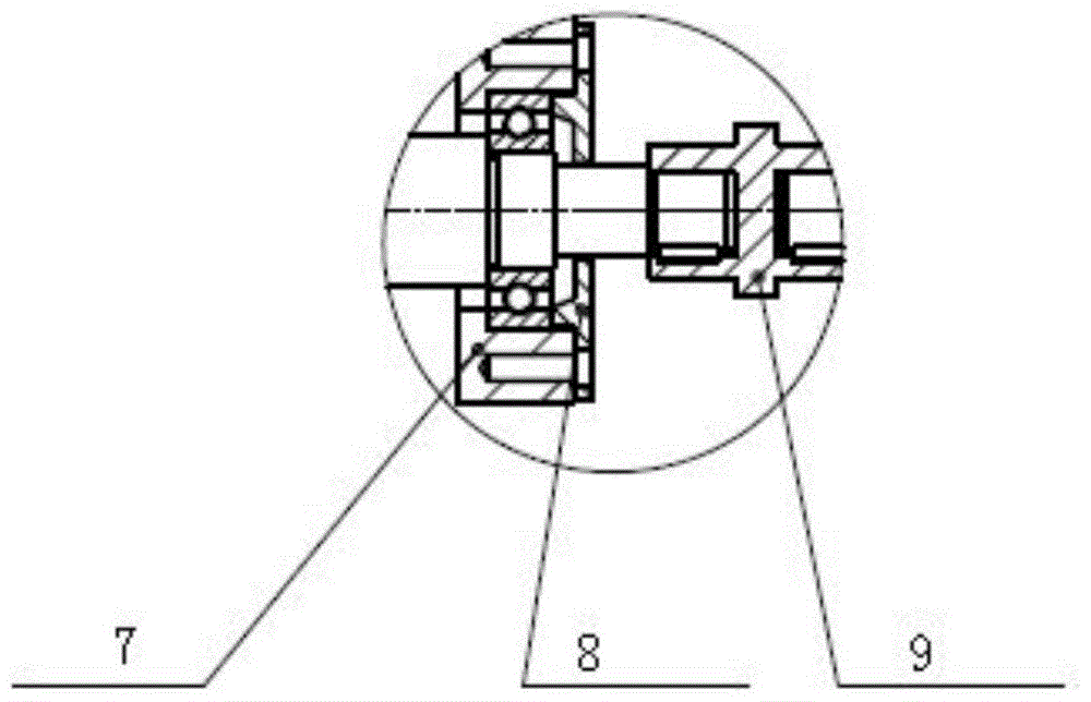
[0029] Refer to attached Figures 1 to 4 It can be seen that the automatic door of the present invention includes a door frame 21 and a door body 20 matched with the door frame 21 . The automatic door also includes an automatic door opening and closing mechanism. The automatic door opening and closing mechanism includes a pulley assembly C installed on the inner wall of the door body 20, a support rod 4 connected to the pulley assembly C, a rotating shaft 6 for fixing the support rod 4, and a fixed rotation The fixed parts A, B of the shaft 6 and the power part 10 for rotating the rotary shaft 6, the fixed parts A, B and the power part 10 are installed on the door frame 21 inside the automatic door or on the wall where the door frame 21 is installed. The power component 10 of the rotating shaft 6 can be an electric motor, a rotating hydraulic cylinder, etc., and the electric motor or rotating hydraulic cylinder is connected to one end of the rotating shaft 6 through a bushing ...


PUM


Abstract

The invention discloses an automatic door which comprises a frame and a body matched with the frame. The body is movably hinged to the frame, and the body can rotate relative to the frame. The automatic door further comprises an automatic door opening and closing mechanism. The automatic door opening and closing mechanism comprises a pulley assembly arranged on the inner wall of the body, a supporting rod connected with the pulley assembly, a rotating shaft for fixing the supporting rod, a fixing part for fixing the rotating shaft and a power part for rotating the rotating shaft, wherein the fixing part and the power part of the rotating shaft are arranged on the inner side of the frame. The invention further discloses a wind driven generator cabin cover with the automatic door. According to the automatic door and the wind driven generator cabin cover with the automatic door, the automatic door opening and closing mechanism is adopted to achieve full-automatic opening and closing of the door. The automatic door of the wind driven generator cabin cover serves as a big opening in the top of the wind driven generator cabin cover, so that replacement of big parts in the wind driven generator cabin cover is facilitated, and unsafe operation of manually pushing and pulling the door is avoided.

Description

technical field [0001] The invention relates to the technical field of doors, in particular to an automatic door and a wind turbine nacelle cover including the automatic door. Background technique [0002] At this stage, with the continuous development of science and technology, automatic doors are more and more widely used in people's lives, especially for large factories and large equipment. In the field of wind power generators, with the extension of the running time of wind turbines, some large parts in the nacelle cover are prone to failure, such as bearings, gearboxes, generators, etc. The top opening of the existing wind turbine nacelle cover is small, which can only be used by maintenance personnel to enter and exit and replace small parts of the unit, but it involves the maintenance and replacement of large parts with high failure rates such as bearings, gearboxes, and generators. It is more difficult, and the upper cover must be removed or the whole machine must b...

Claims


Application Information

Patent Timeline
Patent Type & Authority Patents(China)
IPC IPC(8): E05F15/00E05D13/00F03D80/00
CPCY02E10/72
Inventor 夏全洲于国亮王海龙李英昌
Owner GUODIAN UNITED POWER TECH CHIFENG
Learn More