
Methods and systems for preventing unsafe operations

a technology of unsafe operation and methods, applied in computer control, program control, instruments, etc., can solve problems such as unsafe condition, unsafe condition, unsafe condition, etc., and achieve the effect of preventing unsafe operation and unsafe operation

Active Publication Date: 2018-11-01
GLOBALWAFERS CO LTD
View PDF9 Cites 0 Cited by
  • Summary
  • Abstract
  • Description
  • Claims
  • Application Information

AI Technical Summary

Benefits of technology

Prevents unsafe operations by ensuring that combined machine states do not lead to hazardous conditions, thereby enhancing safety and preventing potential damage to machines and processes.

Problems solved by technology

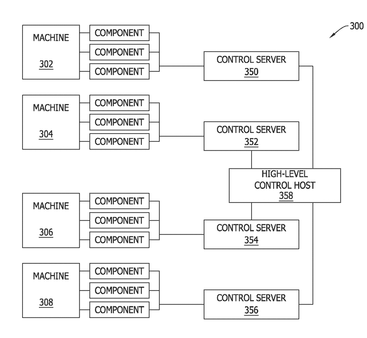
The processor-executable instructions further cause the computing device to perform the steps of determining whether an unsafe condition would result if the first pending output is issued to the first machine in the first state, and issuing the first pending output upon determining that issuing the first pending output would not result in an unsafe condition and blocking the first pending output from being issued upon determining that issuing the first pending output would result in an unsafe condition.
The method further includes determining whether an unsafe condition would result if the first pending output is issued to the first machine in the first state, issuing the first pending output upon determining that issuing the first pending output would not result in an unsafe condition and blocking the first pending output from being issued upon determining that issuing the first pending output would result in an unsafe condition.
The processor-executable instructions further cause the computing device to perform the steps of determining whether an unsafe condition would result if the first pending output is issued to the first machine in the first state, issuing the first pending output upon determining that issuing the first pending output would not result in an unsafe condition and blocking the first pending output from being issued upon determining that issuing the first pending output would result in an unsafe condition.

Method used


Image

  • Methods and systems for preventing unsafe operations
  • Methods and systems for preventing unsafe operations
  • Methods and systems for preventing unsafe operations

Examples


Embodiment Construction

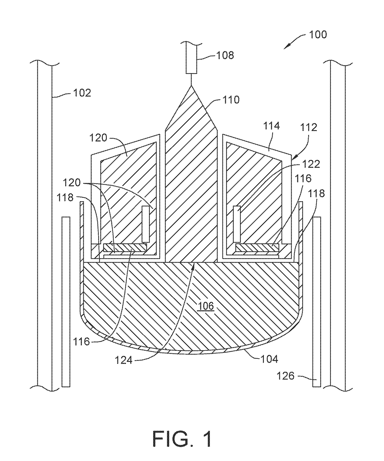
[0017]FIG. 1 is a diagram of a crystal puller 100, which may be controlled by a control server in accordance with an embodiment of the present invention. Crystal puller 100 is used to grow monocrystalline ingots according to the Czochralski method. The Czochralski method is known to those skilled in the art of forming monocrystalline ingots. Crystal puller 100 includes a housing 102, and a quartz crucible 104 in the housing 102 for containing a semiconductor melt 106. The melt contains, for example, silicon. A pulling mechanism 108, such as a shaft or pull wire, secured in housing 102 and adapted to extend toward crucible 104, is adapted to continuously pull a solid monocrystalline ingot or crystal 110 from melt 106. A tubular graphite reflector 112 secured in a growth chamber of housing 102 includes a cover 114 preferably made of graphite and having a central opening sized and shaped for surrounding the growing crystal 110. An annular melt heat exchanger 116 is mounted within cover...


PUM


Abstract

A system for preventing an unsafe operation of a plurality of semiconductor wafer manufacturing machines communicatively coupled to a computing device. The system includes the computing device, which includes a processor coupled to a memory. The memory contains processor-executable instructions that, when executed, cause the computing device to perform the steps of storing, in the memory, a first state of a first machine of the plurality of machines, generating a first pending output to be issued to the first machine, determining whether an unsafe condition would result if the first pending output is issued to the first machine in the first state, issuing the first pending output upon determining that issuing the first pending output would not result in an unsafe condition, and blocking the first pending output from being issued upon determining that issuing the first pending output would result in an unsafe condition.

Description

CROSS-REFERENCE TO RELATED APPLICATIONS[0001]This application is a continuation of and claims the benefit of U.S. patent application Ser. No. 14 / 142,533, filed Dec. 27, 2013, which claims the benefit of priority to U.S. Provisional Patent Application No. 61 / 747,049, filed Dec. 28, 2012, the entire disclosures of which are incorporated herein by reference.BACKGROUND OF THE INVENTION[0002]The field of the invention relates generally to computerized control of machines, and more particularly to preventing instructions for unsafe operations from being issued to machines.[0003]Complex machines, such as those found in a silicon wafer manufacturing plant or other industrial plant, often include multiple components whose operations must be precisely orchestrated to produce a product properly and to prevent unsafe conditions from occurring. Often, not only must the multiple components of a given machine work in concert, interactions between different machines must be coordinated as well. The...

Claims


Application Information

Patent Timeline
Patent Type & Authority Applications(United States)
IPC IPC(8): H01L21/67G05B19/406
CPCH01L21/67288G05B2219/50193G05B2219/45031G05B2219/35283G05B19/406
Inventor ORSCHEL, BENNOWOLFRAM, MIKE
Owner GLOBALWAFERS CO LTD
Learn More