Power tool and operating method for use on the power tool

a technology of power tools and operating methods, which is applied in the direction of multi-purpose tools, manufacturing tools, portable power-driven tools, etc., can solve the problems of easy loss of tool bits, troublesome replacement of tool bits, and large inconvenience for operators, and achieves improved work efficiency, simple structure, and convenient operation

Active Publication Date: 2014-11-06
POSITEC POWER TOOLS (SUZHOU) CO LTD
View PDF3 Cites 18 Cited by
  • Summary
  • Abstract
  • Description
  • Claims
  • Application Information

AI Technical Summary

Benefits of technology

[0213]Comparing with the prior art, the beneficial effects of the present invention are as follows: the handheld power tool according to the present invention has a simple structure which makes rapid change of electric drills and screwdrivers come true and is easy to operate, thus work efficiency is improved.

Problems solved by technology

In particular, under the condition where pre-punched hole is required before tightening a screw, it is required to keep replacement between the drill bit and the screwdriver bit, causing great inconvenience to the operator, not only leading to the trouble of replacing the tool bit, but also easy to lose the tool bit removed and put aside.
Some manual tools can realize storage and rapidly changing of the tool bit, but the operation needs a lot of efforts due to the innate defect of the manual tool, namely small torque, which may result in the disadvantages of operator inclined to tiredness, low efficiency and unsuitability for being used as a professional tool in industrial application.
As a result, many defects emerge, for instance, the need of two chucks, high precision requirement for the connecting structure between the two chucks and the main shaft, difficult manufacturing, and complicated overall structure, big volume and high cost of the double-headed electric drill.
Thus, the operation is troublesome for the procedure of moving the multi-head cartridge can to separate the bit sleeve from the cartridge and then rotating the cartridge can to select the bit.
However, with a compact and small-sized structure, the hand-holding is convenient, but configuration is bound to be complicated, still being a laborious tool.
Moreover, when the machine tool works, the operating slide member is pressed against the tail end of the tool clamp, wherein the tool clamp can rotate, but the operating slide member can't, thus leading to a high slide friction between the operating slide member and the tool clamp, not only affecting work efficiency, but also speeding up the tool's friction, and shortening the service life of the tool.

Method used


Image

  • Power tool and operating method for use on the power tool
  • Power tool and operating method for use on the power tool
  • Power tool and operating method for use on the power tool

Examples


Embodiment Construction

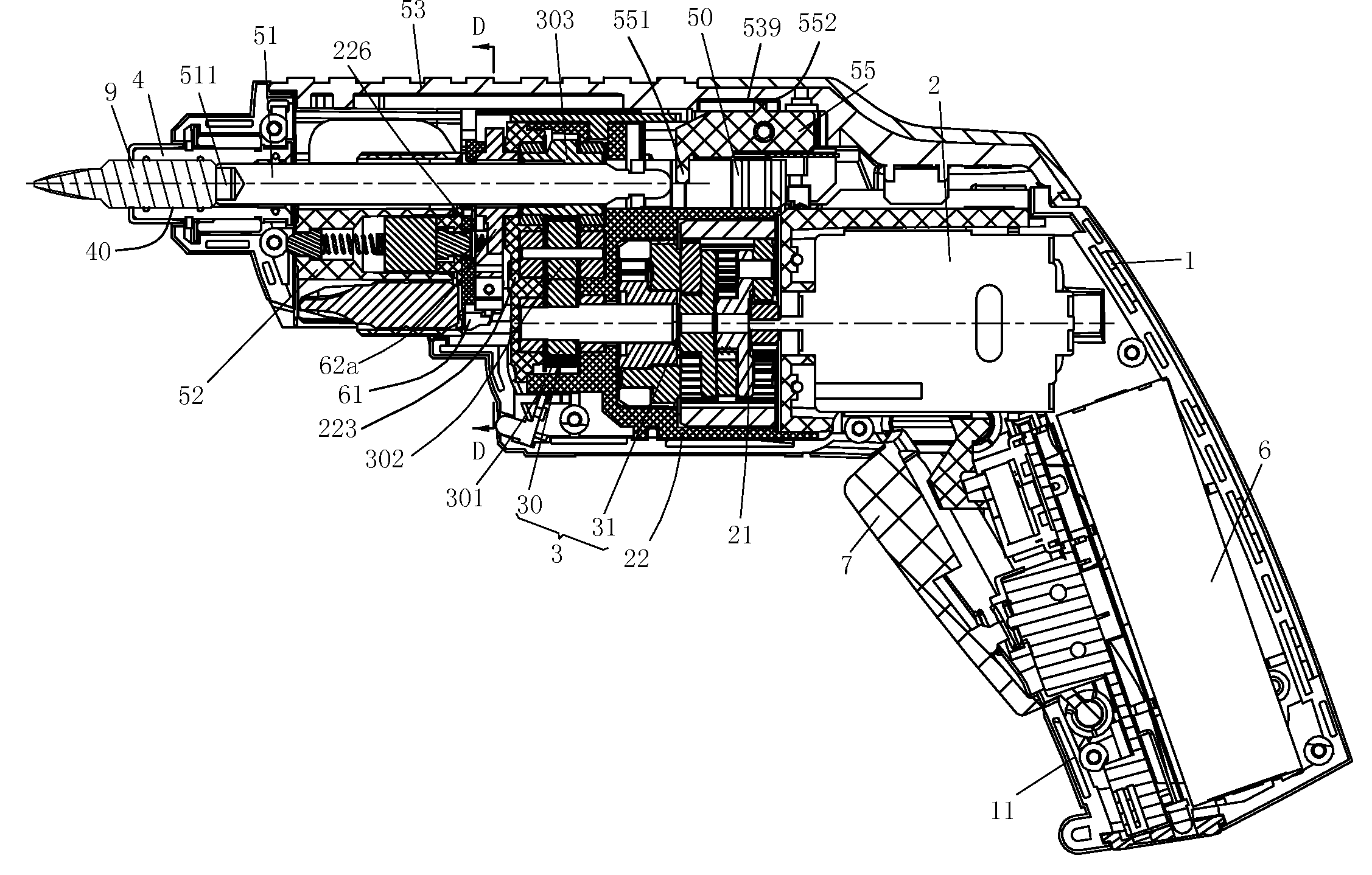
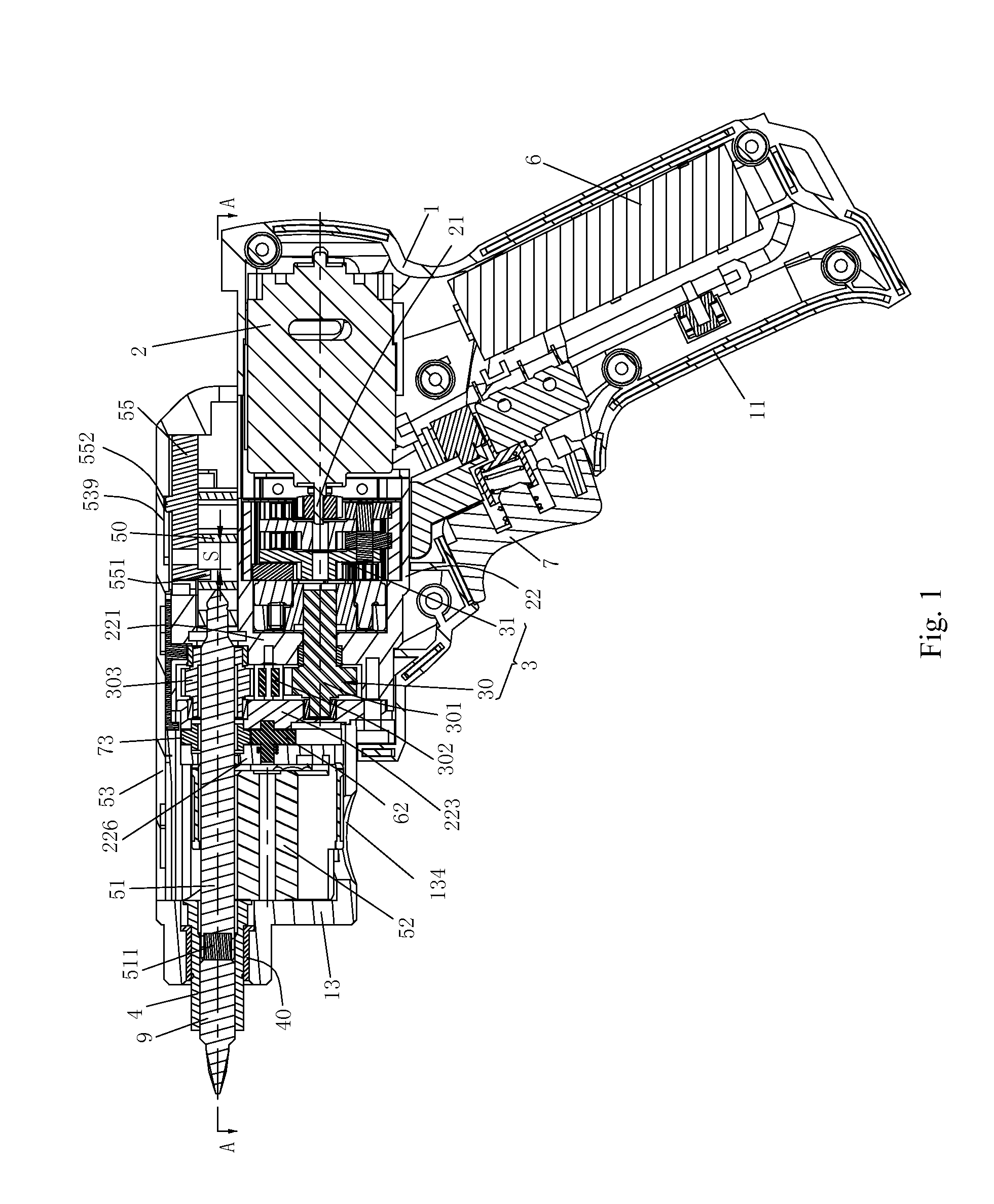
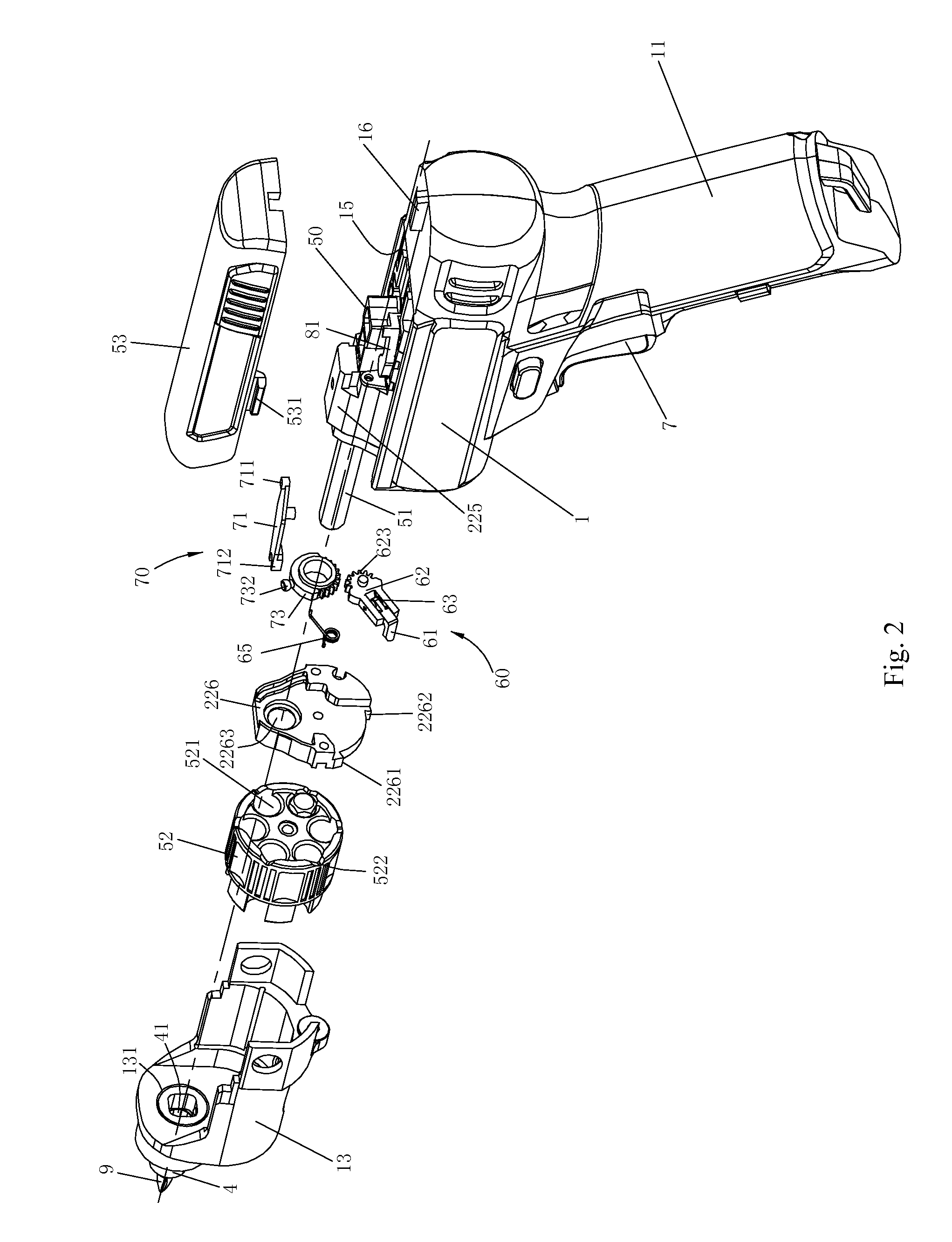
[0304]In the preferred Embodiment I of the present invention power tool, the power tool is a handheld power screwdriver which can be divided into pneumatic screwdrivers, hydraulic screwdrivers and electric screwdrivers by power source. Electric screwdrivers can be further divided into direct-current (DC) ones and alternating-current (AC) ones. The embodiment takes DC screwdrivers for detailed description.

[0305]As shown in FIG. 1 to FIG. 16 is the first embodiment according to the present invention. The DC electric screwdriver comprises a housing 1, a motor 2, a battery 6, a transmission mechanism 3, a connecting member 51, a tool bit supporting assembly and an output shaft 4. The housing 1, formed by assembling two symmetrical semi-housings together with screws (not shown in the figures), has a horizontal component and a handle 11 arranged at an obtuse angle with the horizontal component. The present invention prefers to adopt an angle between 100 degrees to 130 degrees, which provi...


PUM


Abstract

A power tool, comprising: a housing; a motor being disposed in the housing for outputting rotary power; an output shaft having an accommodating hole in the axial direction for holding a tool bit; a transmission mechanism, being disposed between the motor and the output shaft for transmitting rotary power from the motor to the output shaft; a tool bit supporting being disposed in the housing and including several chambers disposed in parallel for holding the tool bit; a connecting member being disposed in the housing and capable of moving axially between a working position where the connecting member passes through one of the chambers and to accommodate the tool bit in the chamber connect the output shaft, and a release position where the connecting member exits and separates from one of the several chambers; and an operating member is arranged on the housing for controlling the axial movement of the connecting member; the power tool further includes an automatic shifting means for adjusting the position of the tool bit supporting in response to the movement of the operating member, wherein the connecting member moves axially to a position that is separated from one of the several chambers, and the cartridge moves to a position where another chamber is axially corresponding to the output shaft under the action of the automatic shifting means.

Description

BACKGROUND OF THE INVENTION[0001]1. Field of the Invention[0002]The present invention relates to a power tool and an operating method for the power tool, especially to a gun-drill type power tool capable of storing and rapidly changing the tool bits and an operating method for rapidly changing the tool bits for the power tool.[0003]2. Description of Related Art[0004]Gun-drill type power tools in the prior art generally comprise electric drills, electric screwdrivers and percussive drills.[0005]An electric screwdriver is a commonly used electric tool for tightening screws onto workpieces. When screws of different sizes are required to be tightened in use, different screwdriver bits may be replaced according to the difference of screw sizes, namely, remove the originally installed screwdriver bit and install a screwdriver bit of another size.[0006]An electric drill is used to drill holes in workpieces. During the operation, the chuck clamps the bit and maintains rotary movement.[0007]...

Claims


Application Information

Patent Timeline
Patent Type & Authority Applications(United States)
IPC IPC(8): B25F5/00B23Q3/157
CPCB25F5/00B23Q3/15713B25F5/001B25B21/00B23Q3/15722B23Q3/15766B23Q2003/1553B25F1/04B25F5/029Y10T483/10Y10T483/1748Y10T483/1798Y10T483/1827
Inventor ANDRIOLO, PAOLOZHANG, SHISONGZHONG, HONGFENGPANG, XIAOLIXU, JINGTAOXIE, MINGJIANMA, YICHUNZHANG, WEIWANG, QINGLIN
Owner POSITEC POWER TOOLS (SUZHOU) CO LTD
Why Eureka
Try Eureka