Ultraviolet Water Disinfection System

a technology of ultraviolet light and disinfection system, which is applied in the field of disinfection of fluids, can solve the problems of difficult rapid turning on and off of such devices, cell apoptosis or programmed death, and the inability of microorganisms to develop immune responses to ultraviolet light radiation, etc., and achieves improved uniform uv exposure, improved disinfection rate, and efficient irradiation

Active Publication Date: 2015-01-08
SENSOR ELECTRONICS TECH
View PDF16 Cites 86 Cited by
  • Summary
  • Abstract
  • Description
  • Claims
  • Application Information

AI Technical Summary

Benefits of technology

[0009]Aspects of the invention provide a solution for treating a fluid, such as water. The solution can determine an ultraviolet transparency of a fluid before or as the fluid enters a disinfection chamber. In the disinfection chamber, the fluid can be irradiated by ultraviolet radiation to harm microorganisms that may be present in the fluid. One or more attributes of the disinfection chamber, fluid flow, and / or ultraviolet radiation can be adjusted based on the transparency to provide more efficient irradiation and / or higher disinfection rates. In addition, various attributes of the disinfection chamber, such as a position of an inlet and outlet, a shape of the disinfection chamber, and / or other attributes of the disinfection chamber, can be utilized to create a turbulent flow of the fluid within the disinfection chamber to promote mixing and improve uniform UV exposure.

Problems solved by technology

The UV radiation does not allow microorganisms to develop an immune response, unlike the case with chemical treatment.
Also, if a sufficient amount of a protein is damaged in a cell of a microorganism, the cell enters apoptosis or programmed death.
However, it is often desirable to combine an ultraviolet purification system with another form of filtration since the UV radiation cannot neutralize chlorine, heavy metals, and other chemical contaminants that may be present in the water.
One of the important issues associated with mercury lamps is that it is difficult to turn on and off such a device rapidly.

Method used


Image

  • Ultraviolet Water Disinfection System
  • Ultraviolet Water Disinfection System
  • Ultraviolet Water Disinfection System

Examples


Embodiment Construction

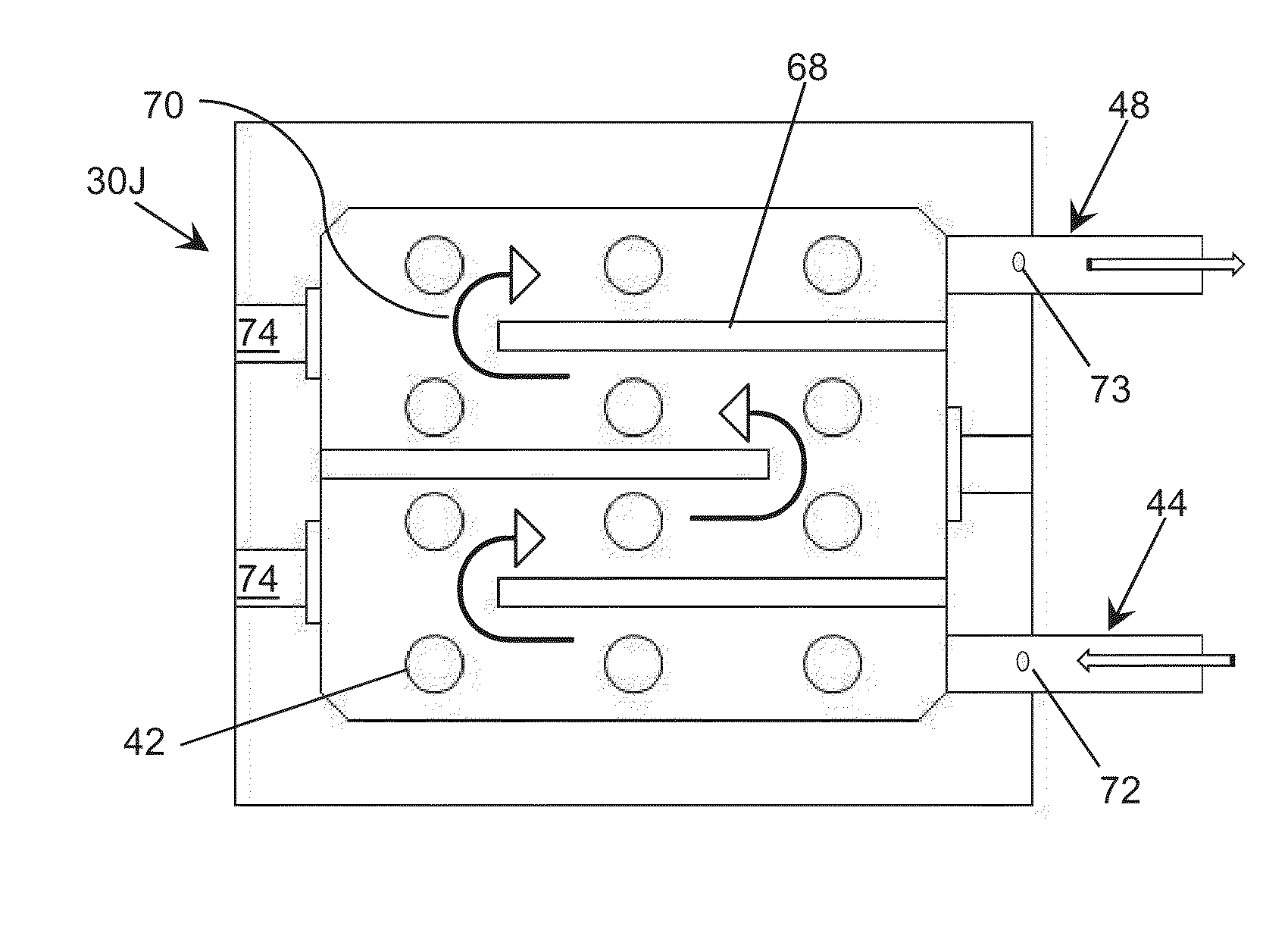
[0030]As indicated above, aspects of the invention provide a solution for treating a fluid, such as water. The solution can determine an ultraviolet transparency of a fluid before or as the fluid enters a disinfection chamber. In the disinfection chamber, the fluid can be irradiated by ultraviolet radiation to harm microorganisms that may be present in the fluid. One or more attributes of the disinfection chamber, fluid flow, and / or ultraviolet radiation can be adjusted based on the transparency to provide more efficient irradiation and / or higher disinfection rates. In addition, various attributes of the disinfection chamber, such as a position of the inlet and outlet, a shape of the disinfection chamber, and / or other attributes of the disinfection chamber can be utilized to create a turbulent flow of the fluid within the disinfection chamber to promote mixing and improve uniform UV exposure. As used herein, unless otherwise noted, the term “set” means one or more (i.e., at least on...


PUM

PropertyMeasurementUnit
wavelengthsaaaaaaaaaa
peak wavelengthaaaaaaaaaa

Abstract

A solution for treating a fluid, such as water, is provided. An ultraviolet transparency of a fluid can be determined before or as the fluid enters a disinfection chamber. In the disinfection chamber, the fluid can be irradiated by ultraviolet radiation to harm microorganisms that may be present in the fluid. One or more attributes of the disinfection chamber, fluid flow, and/or ultraviolet radiation can be adjusted based on the transparency to provide more efficient irradiation and/or higher disinfection rates. In addition, various attributes of the disinfection chamber, such as the position of the inlet(s) and outlet(s), the shape of the disinfection chamber, and other attributes of the disinfection chamber can be utilized to create a turbulent flow of the fluid within the disinfection chamber to promote mixing and improve uniform ultraviolet exposure.

Description

REFERENCE TO RELATED APPLICATIONS[0001]The current application claims the benefit of co-pending U.S. Provisional Application No. 61 / 843,498, titled “Ultraviolet Water Disinfection System,” which was filed on 8 Jul. 2013, and co-pending U.S. Provisional Application No. 61 / 874,969, titled “Ultraviolet Water Disinfection System,” which was filed on 6 Sep. 2014, both of which are hereby incorporated by reference. Aspects of the invention are related to co-pending U.S. patent application Ser. No. 13 / 591,728, which was filed on 22 Aug. 2012, and co-pending U.S. patent application Ser. No. 14 / 157,874, which was filed on 17 Jan. 2014, both of which are hereby incorporated by reference.TECHNICAL FIELD[0002]The disclosure relates generally to disinfection, and more particularly, to a solution for disinfecting a fluid, such as water, using deep ultraviolet light.BACKGROUND ART[0003]Water treatment using ultraviolet (UV) radiation offers many advantages over other forms of water treatment, such...

Claims


Application Information

Patent Timeline
Patent Type & Authority Applications(United States)
IPC IPC(8): C02F1/32G01N21/59C02F1/00
CPCC02F1/325C02F1/003G01N21/59C02F2209/11C02F2303/04C02F2209/001C02F2201/328C02F1/001C02F2201/3222C02F2201/3226C02F2201/3227C02F2201/3228C02F2201/326C02F2209/005C02F2209/05C02F2209/40G01N21/33G01N21/85G01N21/94
Inventor SHTURM, IGORSMETONA, SAULIUSBETTLES, TIMOTHY JAMESBILENKO, YURIGASKA, IGNASDOBRINSKY, ALEXANDERSHUR, MICHAELGASKA, REMIGIJUS
Owner SENSOR ELECTRONICS TECH
Why Eureka
Try Eureka