Multi-antenna structure

Active Publication Date: 2015-01-08
AUDEN TECHNO
View PDF0 Cites 7 Cited by
  • Summary
  • Abstract
  • Description
  • Claims
  • Application Information

AI Technical Summary

Benefits of technology

[0007]In order to solve the above-mentioned problems, an object of the present invention is to provide a multi-antenna structure. Two metal lines are arranged on the two short sides of the grounded metal surface of the base plate. Therefore, the current path of the two short sides is equal to the c

Problems solved by technology

However, the low frequency isolation and correlation of the two antennas are usually not good.
Therefore, the transmissi

Method used


Image

  • Multi-antenna structure
  • Multi-antenna structure
  • Multi-antenna structure

Examples


Embodiment Construction

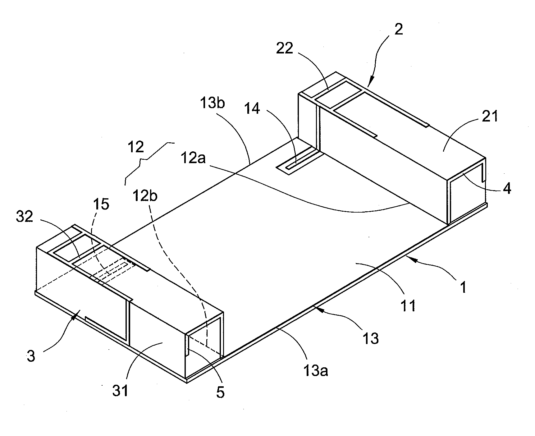
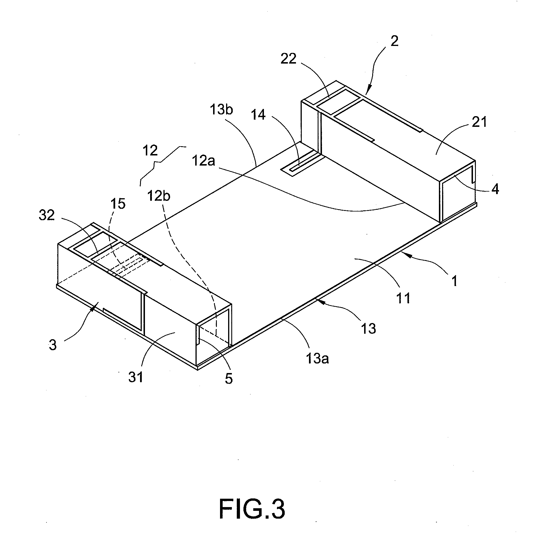
[0025]FIG. 3 shows a diagram of a two-antenna structure of the present invention. FIG. 4 shows an exploded view of the two-antenna structure of the present invention. The multi-antenna structure includes a base plate 1, a first antenna 2, a second antenna 3, a first metal line 4, and a second metal line 5.

[0026]The base plate 1 includes a grounded metal surface 11. The grounded metal surface 11 includes a two-short-side 12 and a two-long-side 13. The two-short-side 12 includes an upper short side 12a and a lower short side 12b. The two-long-side includes a right long side 13a and a left long side 13b. The base plate 1 includes a first signal feed line 14 and a second signal feed line 15. The base plate 1 is a printed circuit board.

[0027]The first antenna 2 is arranged on the base plate 1. The first antenna 2 includes a first rack (first carrier) 21 arranged on the upper short side 12a. The first rack 21 includes a first radiator 22 having a plurality of metal lines. The first radiat...


PUM


Abstract

A multi-antenna structure includes a base plate, a first antenna, a second antenna, a first metal line, and a second metal line. The base plate includes a grounded metal surface. The grounded metal surface includes two short sides and two long sides. The first antenna and the second antenna are arranged on the base plate. The first metal line and the second metal line are electrically connected to the two short sides of the grounded metal surface. A current path of the two short sides is prolonged because of the first metal line and the second metal line. A longitudinal current is equal to a transverse current at a low frequency. A current of the first antenna and a current of the second antenna does not interfere each other. Isolation between the first antenna and the second antenna is improved.

Description

BACKGROUND OF THE INVENTION[0001]1. Field of the Invention[0002]The present invention relates to an antenna, and especially relates to a multi-antenna structure with multi-input multi-output (MIMO).[0003]2. Description of the Related Art[0004]The technology is progressing every day. It is a technology trend that two LTE (long term evolution) / WWAN MIMO antennas are arranged in a mobile device in order to improve communication quality and speed. However, the low frequency isolation and correlation of the two antennas are usually not good. This is because the radiation field of the low frequency is almost omnidirectional. Therefore, the transmission rate cannot be improved greatly.[0005]FIG. 1 shows a diagram of a conventional two-antenna structure. A conventional two-antenna structure includes a base plate 10, a first antenna 20, and a second antenna 30. A grounded metal surface 101 is arranged on the base plate 10. The grounded metal surface 101 includes two short sides 102 and two l...

Claims


Application Information

Patent Timeline
IPC IPC(8): H01Q21/28
CPCH01Q21/28H01Q1/243H01Q1/521H01Q5/371H01Q9/42
Inventor CHEN, CHUN-HUALIU, HSIEN-WEN
Owner AUDEN TECHNO
Why Eureka
Try Eureka