Flexible multiple antenna

A compound antenna, bending technology, applied in the direction of antenna grounding device, radiating element structure, etc., can solve the problem that the antenna cannot be installed, and achieve good grounding effect and good isolation effect

Inactive Publication Date: 2012-08-22
INVENTECSHANGHAI TECH +2
View PDF4 Cites 4 Cited by
  • Summary
  • Abstract
  • Description
  • Claims
  • Application Information

AI Technical Summary

Problems solved by technology

[0007] Due to the above-mentioned problems in the prior art, the purpose of the present invention is to provide a flexibl

Method used


Image

  • Flexible multiple antenna
  • Flexible multiple antenna
  • Flexible multiple antenna

Examples


Embodiment Construction

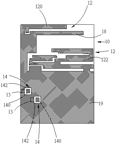
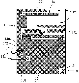
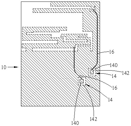
[0059] Such as Figure 1A , 1B and 2 are respectively the front schematic diagram of the flexible composite antenna of the present invention, the schematic diagram of the flexible composite antenna connected to the coaxial cable and the protective layer, and the rear schematic diagram of the flexible composite antenna. In the figure, it includes a flexible substrate 10 , multiple antenna lines 12 , multiple feed-in portions 14 , multiple transmission lines 16 , at least one isolation unit 18 and a ground plane 19 . The ground plane 19 is disposed on one side of the flexible substrate 10 and extends from one edge to the other edge of the flexible substrate 10 . Each antenna line 12 is arranged between the other end edge of one side of the flexible substrate 10 and the ground plane 19, one end of each antenna line 12 is connected to the ground plane 19, and the other end is meandering and bent on the flexible substrate 10, so as to be flexible. The curved substrate 10 is formed...


PUM


Abstract

The invention discloses a flexible multiple antenna. A plurality of antenna circuits with different frequency ranges and a ground plane are arranged on a flexible substrate, the ground plane is provided with feed-in parts which are respectively matched with the antenna circuits, each antenna circuit and the corresponding feed-in part are connected through a transmission line, and an isolation unit is arranged between every two antenna circuits and used for isolating the interactions among the antenna circuits, thereby forming the flexible multiple antenna. The shape of the flexible multiple antenna can be adjusted according to the structure of the installed electronic device, and the flexible multiple antenna can be connected to the electronic device through a coaxial cable or the ground plane is directly connected with the ground plane of the electronic device, thereby achieving better grounding effect.

Description

technical field [0001] The present invention relates to antennas, in particular to a bendable composite antenna. Background technique [0002] In recent years, with the increasing maturity of wireless transmission technology, the application of wireless communication electronic devices is becoming more and more popular, such as wireless mouse, wireless keyboard or mobile phone, etc. Therefore, it is necessary to configure antennas in wireless communication electronic devices for Wireless data transmission and reception. Moreover, the wireless communication electronic device must be able to support the transmission of more and more different wireless network signals, such as global satellite positioning signals, wireless local area network (WLAN) signals, bluetooth signals or digital TV signals, etc. in terms of functions. These wireless signals respectively use different frequency bands. In order to receive the wireless signals of these different frequency bands, many anten...

Claims


Application Information

Patent Timeline
IPC IPC(8): H01Q1/38H01Q1/48
Inventor 李全镒黄麒成吴政勋
Owner INVENTECSHANGHAI TECH
Why Eureka
Try Eureka