Transmitter harmonic cancellation for carrier aggregation/multiband operation

a carrier aggregation/multiband operation and transmitter technology, applied in the direction of transmission, electrical equipment, etc., can solve the problems of spectral regrowth of transmitting signals, unavoidable emissions around the third harmonic of the transmit signal carrier frequency, and degrade the performance of radio devices

a carrier aggregation/multiband operation and transmitter technology, applied in the direction of transmission, electrical equipment, etc., can solve the problems of spectral regrowth of transmitting signals, unavoidable emissions around the third harmonic of the transmit signal carrier frequency, and degrade the performance of radio devices

US20150111510A1Inactive Publication Date: 2015-04-23AVAGO TECH INT SALES PTE LTD

Image

  • Transmitter harmonic cancellation for carrier aggregation/multiband operation
  • Transmitter harmonic cancellation for carrier aggregation/multiband operation
  • Transmitter harmonic cancellation for carrier aggregation/multiband operation

Examples


Embodiment Construction

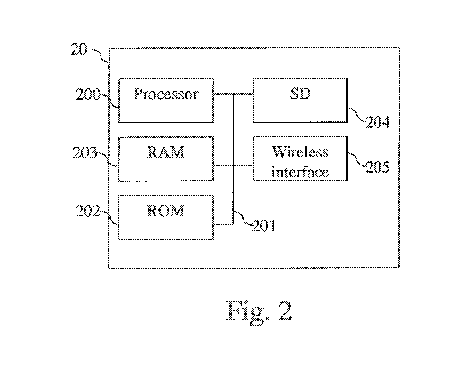
[0054]FIG. 2 schematically represents an architecture of a radio device 20 in which the present invention is implemented.

[0055]The radio device 20 includes the following components interconnected by a communications bus 201: a processor, microprocessor, microcontroller or CPU (Central Processing Unit) 200; a RAM (Random-Access Memory) 203; a ROM (Read-Only Memory) 202; an SD (Secure Digital) card reader 204, or any other device adapted to read information stored on storage means; and a wireless interface 205.

[0056]The wireless interface 205 allows the radio device 20 to wirelessly communicate with another radio device.

[0057]CPU 200 is capable of executing instructions loaded into RAM 203 from ROM 202 or from an external memory, such as an SD card. When the radio device 20 is powered on, CPU 200 reads instructions from RAM 203 and executes the read instructions. The instructions form one computer program that causes CPU 200 to perform some or all of the steps of the algorithm describ...


PUM


Abstract

A method and apparatus for cancelling, from signals received by a radio device in a first frequency band, interference generated by the radio device in the first frequency band when the radio device transmits simultaneously radio signals on at least a second frequency band.

Description

TECHNICAL FIELD[0001]The present invention generally relates to a method and a device for cancelling interference from signals received by a radio device in a first frequency band, while interference is generated by the radio device when the radio device simultaneously transmits radio signals on at least a second frequency band.BACKGROUND INFORMATION[0002]In new wireless cellular telecommunication networks and in particular in the Third Generation Partnership Project (3GPP), Long Term Evolution advanced, new features are considered. One of the new features is Carrier Aggregation. Downlink Aggregation enables radio devices to transmit or receive simultaneously on two frequencies in two different frequency bands, thus doubling the theoretical throughput in Downlink.[0003]The radio device may receive simultaneously signals in plural frequency bands which are different from the frequency bands the radio device uses for transmitting radio signals.[0004]Depending on the allocated frequenc...

Claims


Application Information

Patent Timeline
23 Apr 2015
Publication
US20150111510A1
IPC
H04B1/04
CPC
H04B2001/0408; H04B1/0475; H04B1/525; H04B1/1027; H04B1/123; H04B2001/1072
Inventors
BAUDIN, PIERRE; GUENAIS, MIKAEL