projector

Active Publication Date: 2015-08-27
SEIKO EPSON CORP
View PDF2 Cites 8 Cited by
  • Summary
  • Abstract
  • Description
  • Claims
  • Application Information

AI Technical Summary

Benefits of technology

[0007]An advantage of some aspects of the invention is to accurately detect illuminance in a space wh

Problems solved by technology

When a projector is provided with both the obstacle sensor and the illuminance sensor, light emitted from the ob

Method used


Image

  • projector
  • projector
  • projector

Examples


Example

[0027]Embodiments of the invention will be described below with reference to the accompanying drawings. Components corresponding to each other in the drawings have the same reference characters, and no duplicated description will be made.

1. Outline

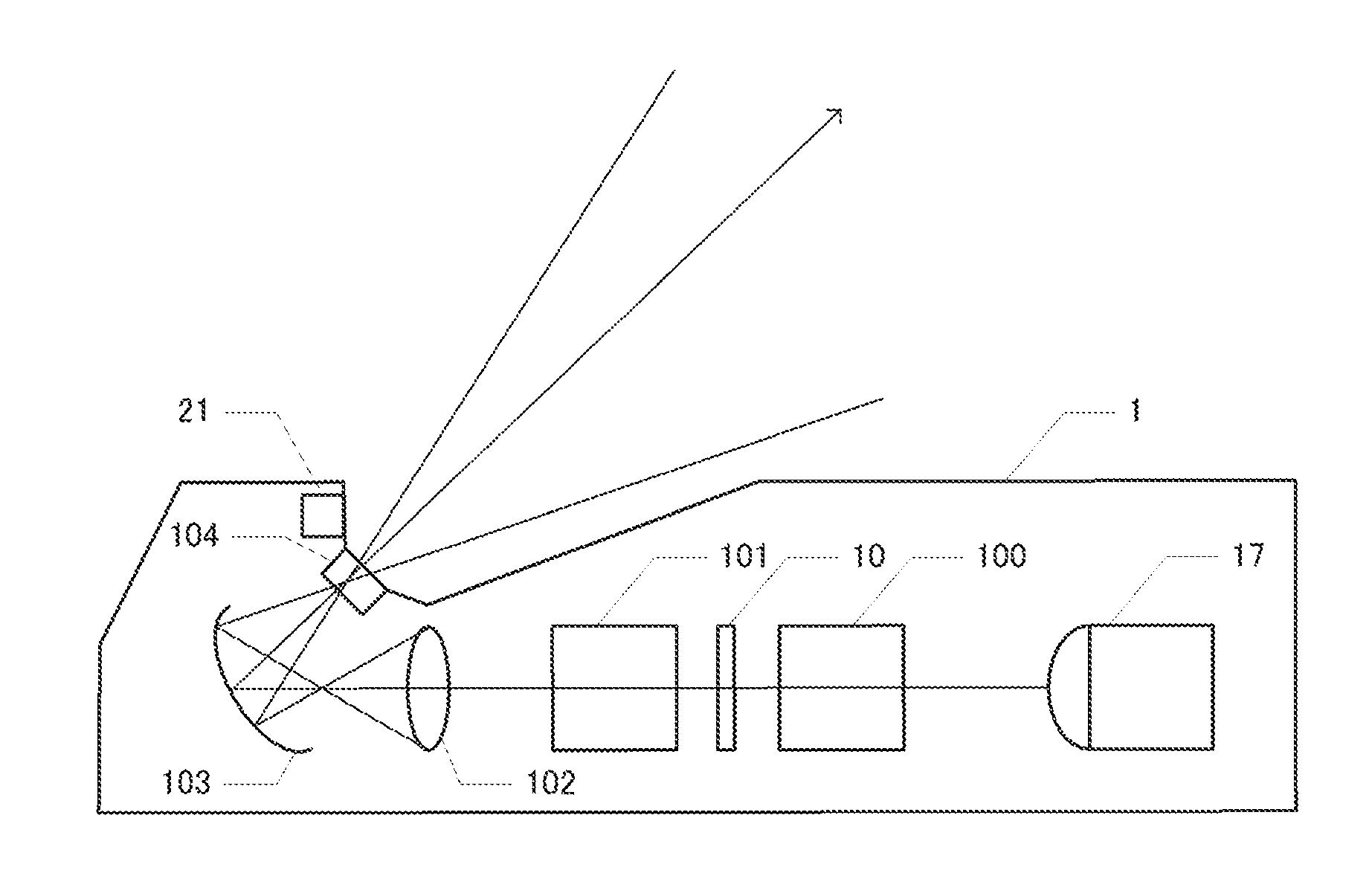
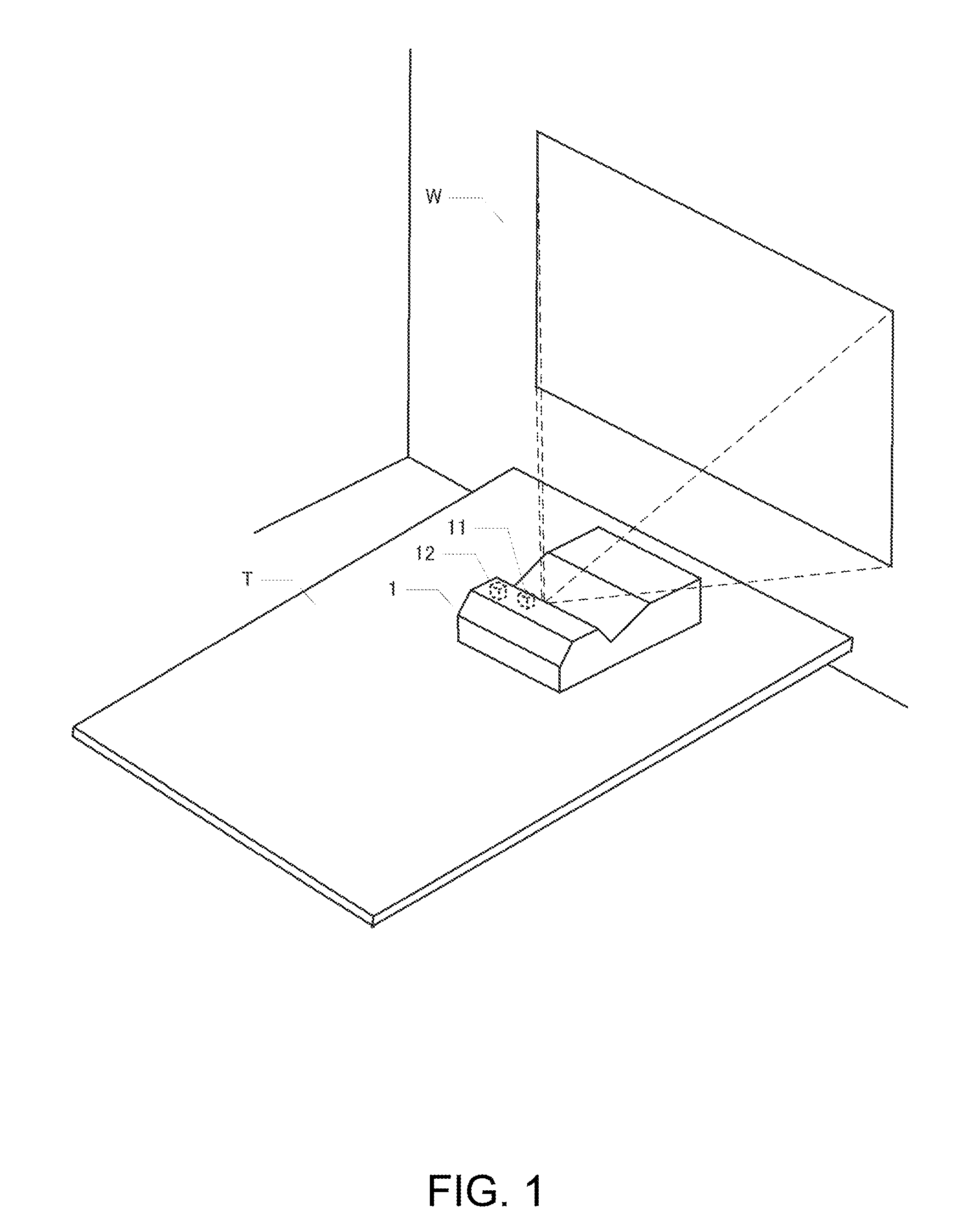
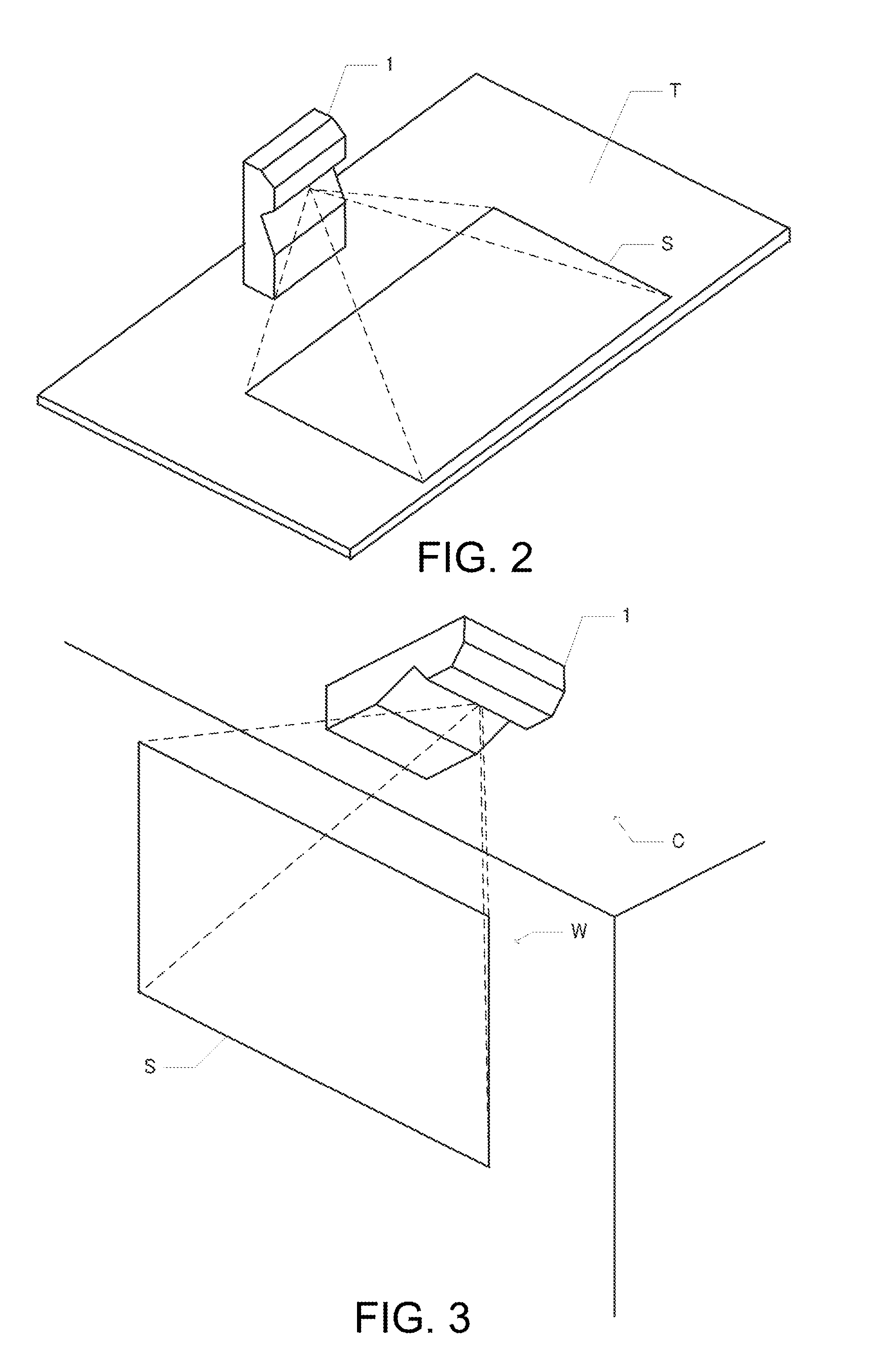
[0028]A projector 1 according to an embodiment of the invention is installed on a ceiling C, a wall W, a table T, or any other surface and projects an image on the wall W, the table T, a dedicated screen, or any other surface, as shown in FIGS. 1 to 3. A window through which the projector 1 projects light is provided on the side that forms the upper surface of the projector 1 when it is installed on a horizontal surface, such as the table T, as shown in FIG. 1. Therefore, when the projector 1 is installed on a horizontal surface, such as the table T, the window may be accidentally blocked with an obstacle. If the window through which light is projected is blocked, for example, with a sheet of paper that tends to absorb light, the optical e...


PUM


Abstract

Illuminance in a space where a projector projects an image is accurately detected with failure of the projector due to heat accumulation prevented. The projector includes a window that allows light to pass therethrough, a projection section that projects light through the window to project an image, an illuminance sensor that detects illuminance in a space where the image is projected, an obstacle sensor that has a light emitting section and a light receiving section, the light emitting section emitting second light, the light receiving section receiving the second light, the obstacle sensor detecting an obstacle based on an output from the light receiving section, and a control section that disables the detection of the illuminance during a period for which the light emitting section emits the light.

Description

[0001]The entire disclosure of Japanese Patent Application No. 2014-036420, filed Feb. 27, 2014 is expressly incorporated by reference herein.BACKGROUND[0002]1. Technical Field[0003]The present invention relates to a projector.[0004]2. Related Art[0005]As disclosed in Japanese Patent No. 3,886,521, there is a known technology for preventing failure of a projector due to heat accumulation by providing an obstacle sensor in a position close to a window of the projector through which light is projected. Further, as disclosed in JP-A-2012-134601, there is a known technology for detecting illuminance in a space where a projector projects an image and adjusting the image quality in accordance with the detected illuminance.[0006]When a projector is provided with both the obstacle sensor and the illuminance sensor, light emitted from the obstacle sensor prevents the detection of illuminance, undesirably resulting in improper image quality adjustment.SUMMARY[0007]An advantage of some aspects...

Claims


Application Information

Patent Timeline
IPC IPC(8): H04N9/31
CPCH04N9/3194H04N9/3155G03B21/2053G03B21/00G03B21/28
Inventor YOSHIDA, SHINGO
Owner SEIKO EPSON CORP
Why Eureka
Try Eureka