Magnetostrictive torque sensor and electric power steering apparatus

Active Publication Date: 2008-09-11
HONDA MOTOR CO LTD
View PDF2 Cites 16 Cited by
  • Summary
  • Abstract
  • Description
  • Claims
  • Application Information

AI Technical Summary

Benefits of technology

[0013]According to the second aspect of the present invention, the section secondary moment of the rotating shaft at the part closer to the bearing is made greater than the section secondary moment at the far part such that bending moments of the rotating shaft at the parts on which the detection means are respectively placed a

Problems solved by technology

However, in such a magnetostrictive torque sensor, one end of the rotating shaft cannot be made completely open, but the one end is coupled to the steering wheel, so that when strongly

Method used


Image

  • Magnetostrictive torque sensor and electric power steering apparatus
  • Magnetostrictive torque sensor and electric power steering apparatus
  • Magnetostrictive torque sensor and electric power steering apparatus

Examples


Example

First Embodiment

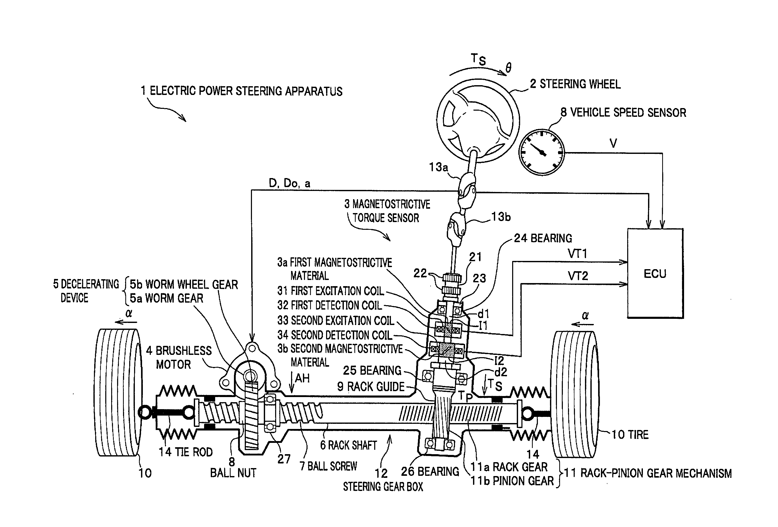
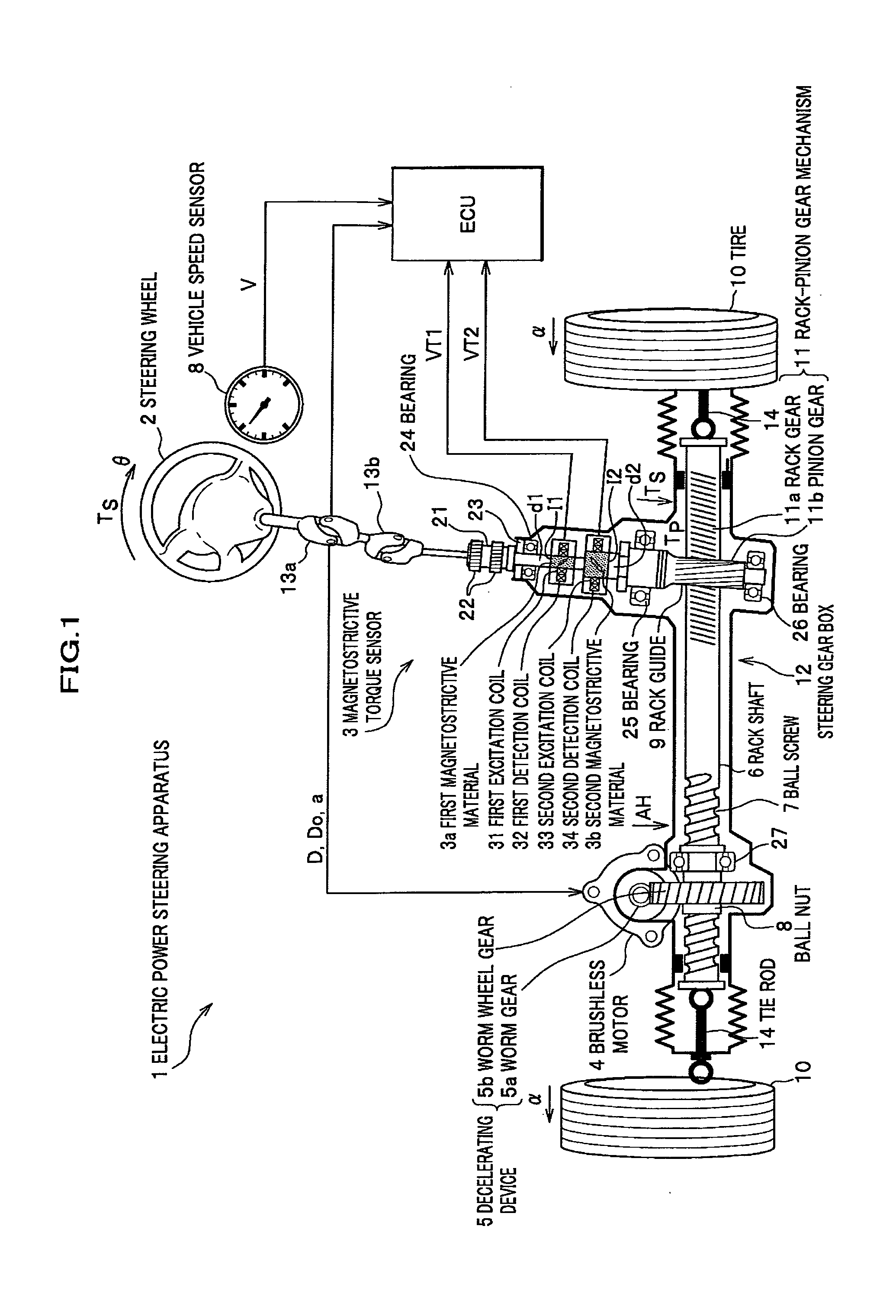
[0031]FIG. 1 shows an entire configuration of an electric power steering apparatus (EPS) 1 according to a first embodiment of the present invention. A steering wheel 2 is coupled to the upper end of a steering shaft 21 via universal joints 13a, 13b. A pinion gear 11b is secured to the lower end of the steering shaft 21. The pinion gear 11b engages with a rack gear 11a, and the rack gear 11a and the pinion gear 11b form a rack-pinion gear mechanism 11. The rack-pinion gear mechanism 11 converts steering torque Ts of the steering shaft 21 into thrust of an axis direction of a rack shaft 6. The rack gear 11a is made by cutting into the rack shaft 6.

[0032]A ball screw 7 is also made by cutting into the rack shaft 6, and a ball nut 8 is provided on the inner side of a worm wheel gear 5b. The rack shaft 6 and the worm wheel gear 5b engage the ball nut 8 via a plurality of re-circulating balls (not shown). The outer teeth of the worm wheel gear 5b engage a worm gear 5a. The...

Example

Second Embodiment

[0058]FIG. 6A is a diagram of the configuration of a magnetostrictive torque sensor according to a second embodiment of the present invention. The magnetostrictive torque sensor of the second embodiment differs from the magnetostrictive torque sensor of the first embodiment in that not both ends of the rotating shaft 21 are rotatably supported, but the upper end of the rotating shaft 21 is an open end, specifically, in that the bearing 24 of FIG. 3 is omitted. However, the upper end of the rotating shaft 21 is not actually a completely open end, but the steering wheel 2 is coupled to the upper end, and a force G from the steering wheel 2 acts on the upper end of the rotating shaft 21 via the universal joints 13a, 13b when strongly turning the steering wheel as in performing stationary steering, e.g., while driving the vehicle into the garage.

[0059]The rotating shaft 21 of the magnetostrictive torque sensor 3 is rotatably supported by the bearings 25, 26. The first m...

Example

Third Embodiment

[0064]FIG. 8 is a diagram of the configuration of an electric power steering apparatus having a magnetostrictive torque sensor according to a third embodiment of the present invention. The electric power steering apparatus of the third embodiment differs from the electric power steering apparatus of the first embodiment in that instead of the rack-pinion gear mechanism 11, the decelerating device 5 is provided in between the bearings 25, 26. Consequently, the rack-pinion gear mechanism 11 is provided below the bearing 26 as similar to the first embodiment, but the mechanism 11 is located also below the bearing 25. The pinion gear 11b is rotatably supported by a new bearing 26a. Further, the universal joints 13a, 13b and the tightener 22 have been moved from above the bearing 24 to below the bearing 26. According to the third embodiment, the auxiliary torque AH can be applied not to the rack shaft 6 but directly to the rotating shaft 21. By this means, the force F as ...


PUM


Abstract

A magnetostrictive torque sensor includes a rotating shaft rotatably supported; magnetostrictive materials provided on a surface of the rotating shaft, magnetic permeability of which changes according to the magnitude of rotary torque acting on the rotating shaft; and at least two detection coils provided to the rotating shaft, which detect change in the magnetic permeability of the magnetostrictive materials to output in the form of electrical change. Section secondary moments of the rotating shaft at its parts on which the detection coils are respectively placed are different from each other.

Description

CROSS REFERENCE TO RELATED APPLICATIONS[0001]This application claims the foreign priority benefit under Title 35, United States Code, §119(a)-(d) of Japanese Patent Application No. 2007-056596, filed on Mar. 7, 2007 in the Japan Patent Office, the disclosure of which is herein incorporated by reference in its entirety.BACKGROUND OF THE INVENTION[0002]1. Field of the Invention[0003]The present invention relates to a magnetostrictive torque sensor which detects change in the magnetic permeability of a magnetostrictive material and outputs the change in the form of electrical change, thereby detecting torque applied to the rotating shaft, and an electric power steering apparatus including this magnetostrictive torque sensor mounted therein.[0004]2. Description of the Related Art[0005]Magnetostrictive torque sensors are mounted in electric power steering apparatuses for vehicles. The electric power steering apparatus is a support apparatus which, when a driver turns the steering wheel w...

Claims


Application Information

Patent Timeline
IPC IPC(8): G01L3/00
CPCB62D6/10G01L3/105G01L5/221G01L3/102
Inventor SHIMIZU, YASUO
Owner HONDA MOTOR CO LTD
Why Eureka
Try Eureka