Moving state detecting device

Active Publication Date: 2012-02-16
FURUNO ELECTRIC CO LTD
View PDF4 Cites 18 Cited by
  • Summary
  • Abstract
  • Description
  • Claims
  • Application Information

AI Technical Summary

Benefits of technology

[0031]According to this invention, an acceleration can highly accurately be obtained by dividing the acceleration for every frequency band, therefore, an attached angle of an accelero

Problems solved by technology

However, the attached angle calculating devices disclosed in the Patent Documents 1 and 2 described above are not for detecting the attached angle only from an output value of the accelerometer but for detecting by using, for example, an angular velocity obtained from a gyroscope or an angular rate sensor, and a vehicle speed pulse obtained from the movable body.
Further, although the acceleration that is outputted to/from the accelerometer contains unnecessary components such as a bias

Method used


Image

  • Moving state detecting device
  • Moving state detecting device
  • Moving state detecting device

Examples


Example

[0037]A moving state detecting device according to a first embodiment of the present invention is described in detail with reference to the drawings. The moving state detecting device according to this embodiment is used for various kinds of navigation apparatuses, such as a vehicle-mounted navigation apparatus and a PND (Personal Navigation Device).

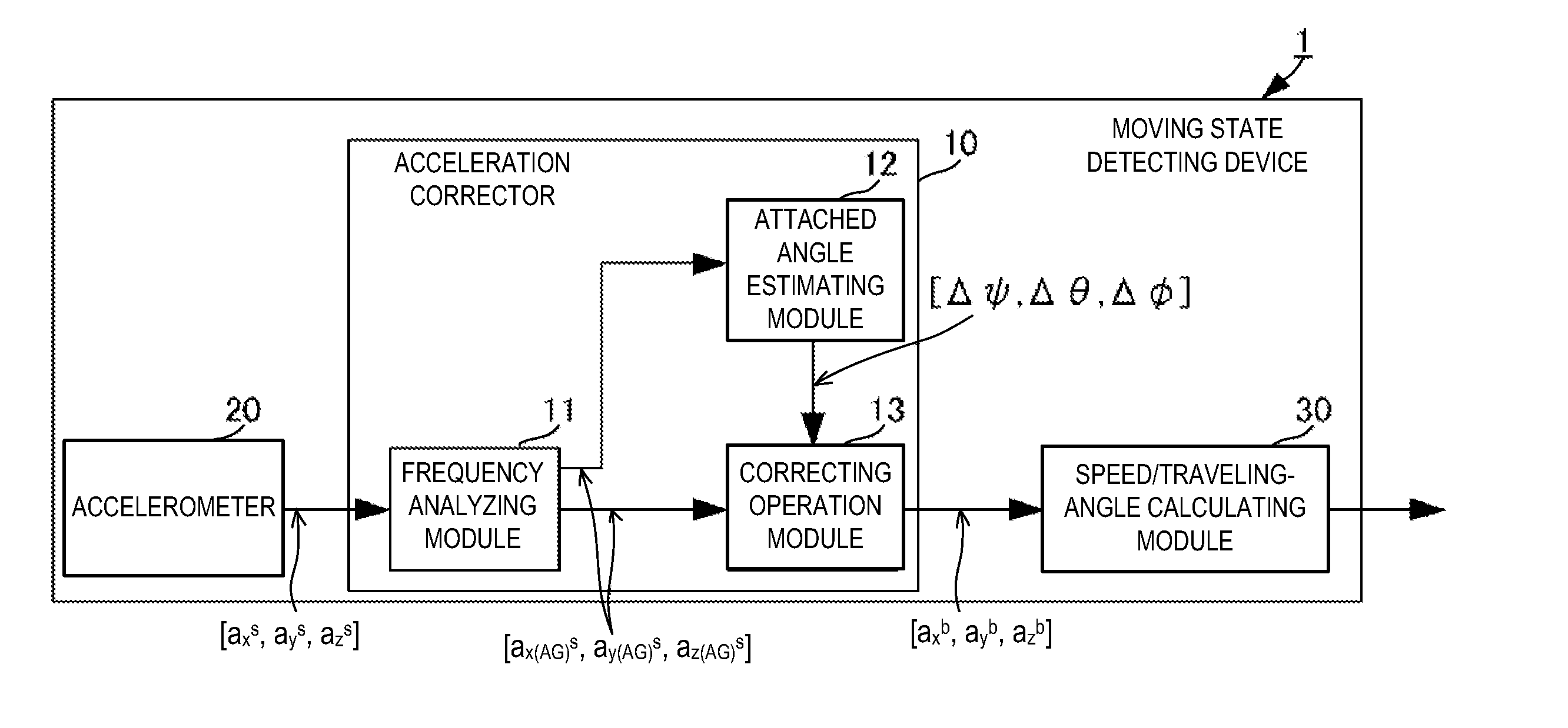
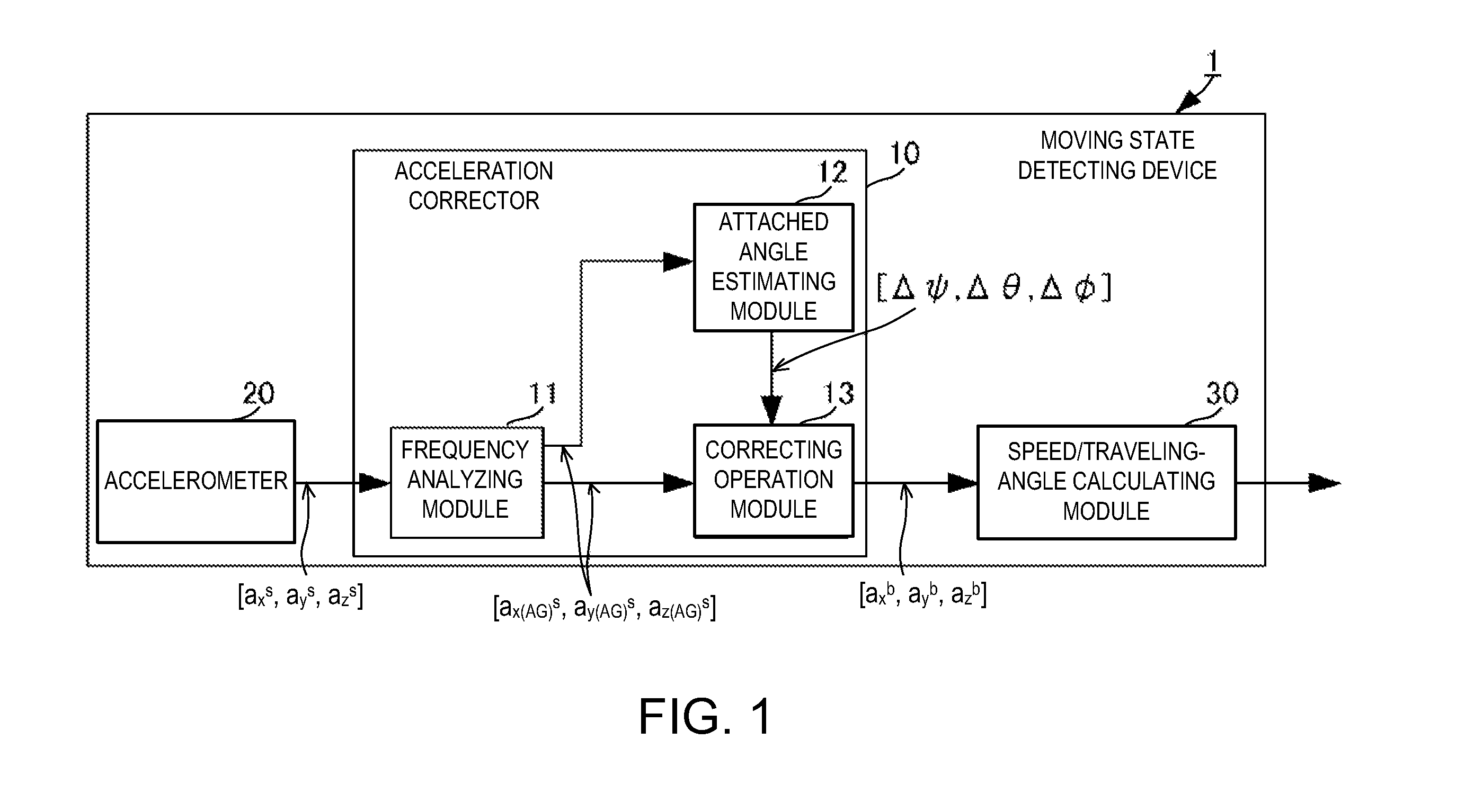
[0038]FIG. 1 is a block diagram showing a main configuration of a moving state detecting device 1 of this embodiment.

[0039]As shown in FIG. 1, the moving state detecting device 1 includes an accelerometer 20, an acceleration corrector 10, and a speed / traveling-angle calculating module 30. The moving state detecting device 1 is fixedly installed in a movable body such as a vehicle. Note that, the moving stated detecting device 1 of this embodiment is for detecting a speed and a traveling angle (a traveling pitch angle, a traveling roll angle, and a traveling azimuth angle (yaw angle)) of the movable body; however, if it is for, for exampl...

Example

[0088]Next, a moving state detecting device according to a second embodiment is described in detail with reference to the drawings.

[0089]FIG. 4 is a block diagram showing a main configuration of the moving state detecting device 1′ of this embodiment.

[0090]The moving state detecting device 1′ of this embodiment is the moving state detecting device 1 described in the first embodiment with a stop detecting module 40 added thereto. Hereinafter, only the stop detecting module 40 and parts relating thereto are explained.

[0091]The stop detecting module 40 acquires a stop detection acceleration [ax(AN)s, ay(AN)s, az(AN)s] comprised of a sum of the movement acceleration frequency component and the noise frequency component of the sensor coordinate system acceleration [axs, ays, azs]. The stop detecting module 40 stores, in advance, thresholds (≠0) for detecting a stop, for a front-and-rear direction component ax(AN)s and a left-and-right direction component ay(AN)s of the stop detection acc...

Example

[0093]Next, a moving state detecting device according to a third embodiment is described in detail with reference to the drawings.

[0094]FIG. 5 is a block diagram showing a main configuration of the moving state detecting device 100 of this embodiment.

[0095]The moving state detecting device 100 of this embodiment calculates a position and a moving azimuth of the movable body based on various kinds of data from a GPS receiver 102 and angle speed data from a gyroscope 101, in addition to the speed and the traveling angle obtained with the configuration of the moving state detecting device 1 described in the first embodiment. Therefore, in the description below, description of parts that are same as the configuration of the moving state detecting device 1 described in the first embodiment are omitted and only different parts are described.

[0096]The moving state detecting device 100 includes an azimuth calculating module 50 and a position calculating module 60 as well as the configuratio...


PUM


Abstract

To accurately calculate an attached angle of an accelerometer and accurately correct an acceleration that is obtained from the accelerometer: a frequency analyzing module of an acceleration corrector divides a sensor coordinate system acceleration into a bias frequency component, a gravity frequency component, a movement acceleration frequency component, and a noise frequency component, through a wavelet transform. The frequency analyzing module outputs a sum component of the gravity frequency component and the movement acceleration frequency component to an attached angle estimating module and a correcting operation module. The attached angle estimating module estimation-calculates the attached angle of an accelerometer and outputs it to the correcting operation module. The correcting operation module corrects the acceleration, which is including of the sum component of the gravity frequency component and the movement acceleration frequency component, based on the estimation-calculated attached angle to calculate a movable body coordinate system acceleration.

Description

TECHNICAL FIELD[0001]The present invention relates to a moving state detecting device that is attached in a moving body and detects a moving state such as a speed and a pitch angle of the moving body.BACKGROUND ART[0002]Currently, various kinds of navigation apparatuses that are attached to to movable bodies, such as automobiles, and detect a position, a traveling speed, and a traveling direction of the movable body and displaying information for assisting in traveling toward a destination have been devised. With such navigation apparatuses, a position of the device itself is detected based on positioning signals from positioning satellites, such as GPS satellites, and a moving state of a movable body is detected by using speed information that the movable body already has, such as a vehicle speed pulse in an automobile, and azimuth information that is obtained by, for example, a gyroscope.[0003]Meanwhile, recently, as alternatives to the navigation apparatuses described above that ...

Claims


Application Information

Patent Timeline
IPC IPC(8): G01P21/02G01P21/00G06F19/00
CPCG01P21/00G01C21/16G01C21/185G01P15/0802G01C25/005
Inventor TODA, HIROYUKIYOSHITAKE, KEN
Owner FURUNO ELECTRIC CO LTD
Why Eureka
Try Eureka