Back-illuminated distance measuring sensor and distance measuring device

Active Publication Date: 2010-08-12
HAMAMATSU PHOTONICS KK
View PDF4 Cites 17 Cited by
  • Summary
  • Abstract
  • Description
  • Claims
  • Application Information

AI Technical Summary

Benefits of technology

[0029]Highly accurate distance detection can be carried out by the back-illuminated dista

Problems solved by technology

If the charge distribution speed is slow, there is a problem in which accurate distance measurement cannot be brought about without securing a sufficient S/N ratio since the number of times of a charge distribution that composes one frame is unavoidably decreased.
In this case, if the carrier drawing-in action to a plurality of potential wells is changed over at a high speed, a majority of the carriers cannot reach the potential wells, wherein although the charge quantity in the potential well i

Method used


Image

  • Back-illuminated distance measuring sensor and distance measuring device
  • Back-illuminated distance measuring sensor and distance measuring device
  • Back-illuminated distance measuring sensor and distance measuring device

Examples


Example

Embodiment 1

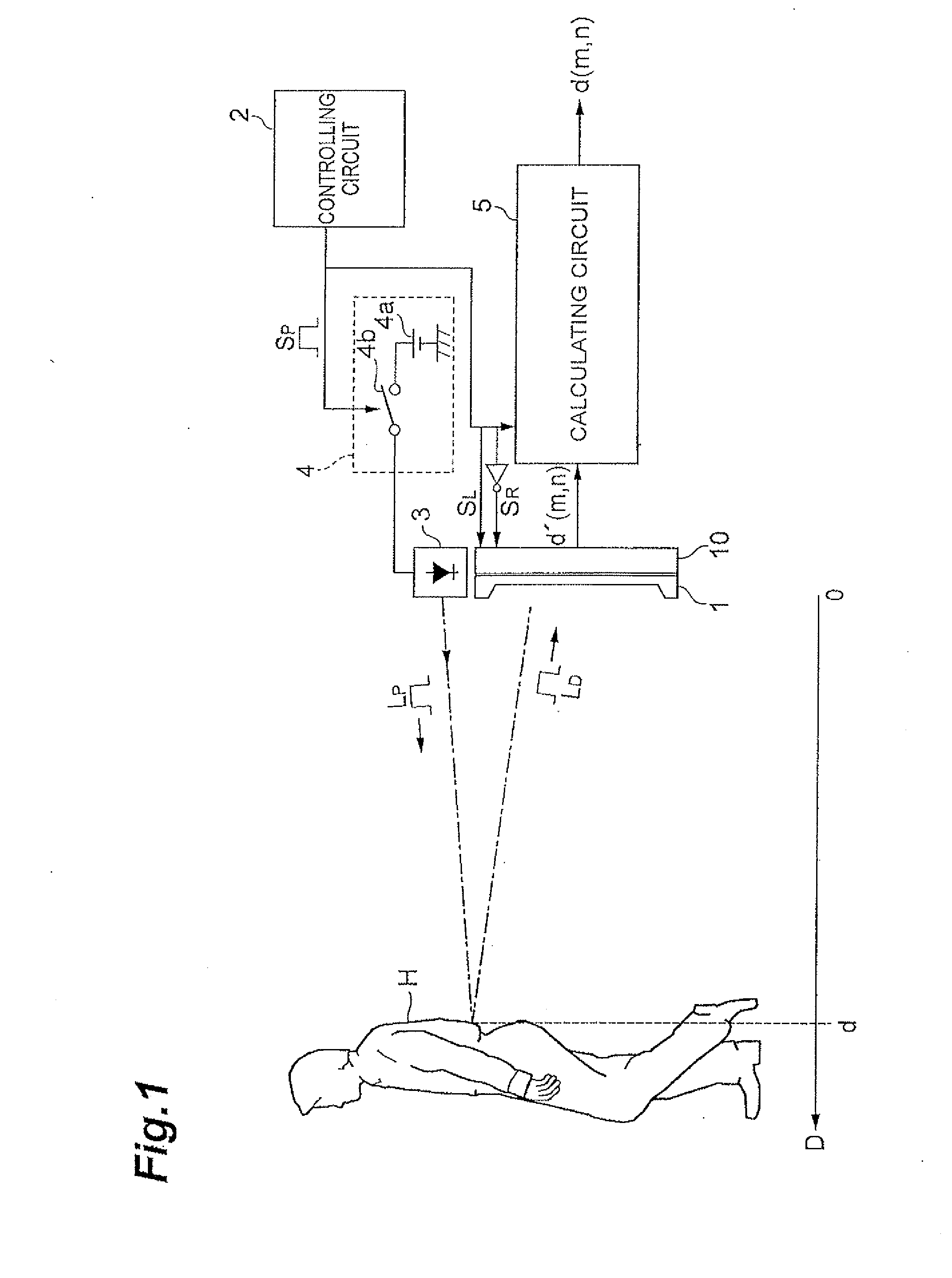
[0091]FIG. 1 is a schematic view showing the structure of a distance measuring sensor.

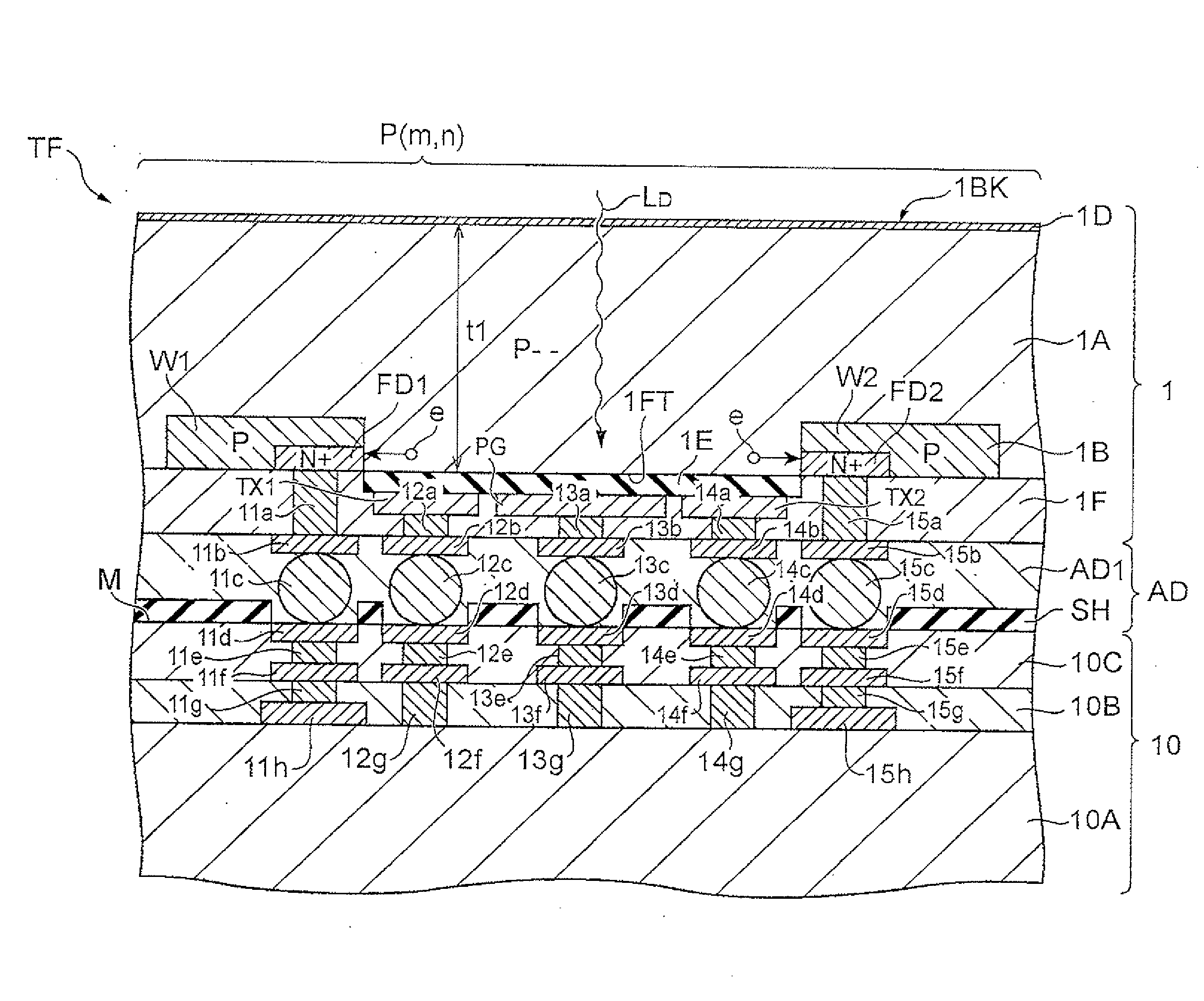
[0092]The distance measuring device includes a back-illuminated distance measuring sensor 1, a light source 3 for emitting near-infrared light, a driving circuit 4 for giving a pulse drive signal SP to the light source 3, a controlling circuit 2 for giving detection gate signals SL, SR synchronized with the pulse drive signal SP to the first and the second gate electrodes (TX1, TX2: Refer to FIG. 5) included in respective pixels of the back-illuminated distance measuring sensor 1, and a calculating circuit 5 for calculating the distance to an object H such as a pedestrian based on signals d′ (m,n) showing distance information read from the first and the second semiconductor areas (FD1, FD2: Refer to FIG. 5) of the back-illuminated distance measuring sensor 1. The distance in the horizontal direction D from the back-illuminated distance measuring sensor 1 to the object H is regarded as d...

Example

Embodiment 2

[0169]The structure of a distance measuring device according to Embodiment 2 is identical to that described in FIG. 1. The distance measuring device is different from the device described in FIG. 1 only in the detail of the back-illuminated distance measuring sensor 1 that composes the distance measuring device. The distance measuring device is provided with the controlling circuit 2, light source 3, driving circuit 4 and calculating circuit 5, which are described in FIG. 1.

[0170]FIG. 15 is a plan view showing a distance measuring sensor according to Embodiment 2.

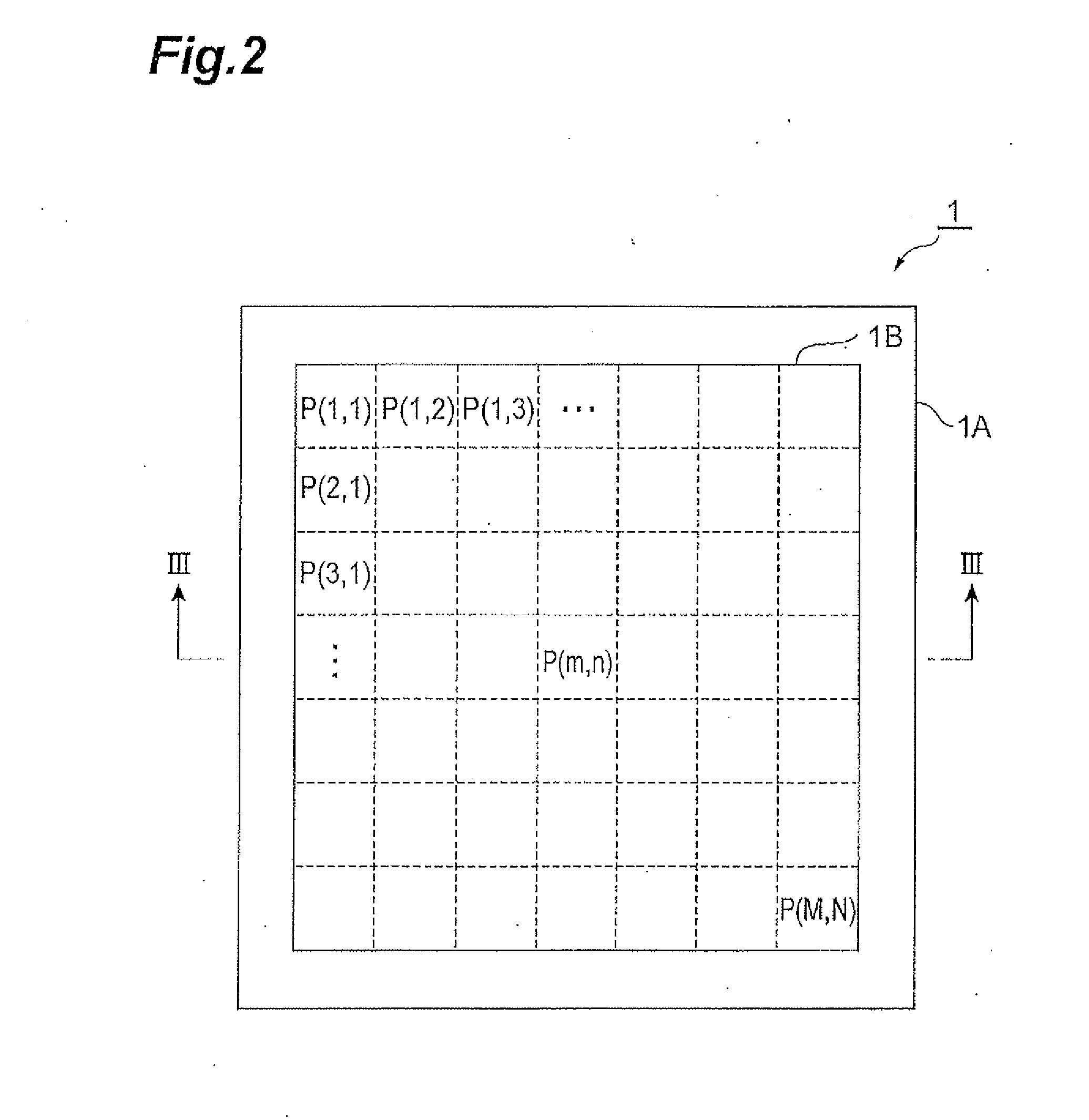
[0171]The back-illuminated distance measuring sensor 1 is provided with a semiconductor substrate 1A having a pickup area 1B composed of a plurality of two-dimensionally arrayed pixels P (m,n). Two charge quantities (Q1,Q2) are output from respective pixels P (m,n) as signals d′ (m,n) having the above-described distance information. Since the respective pixels P (m,n) output signals d′(m,n) responsive to the dis...

Example

Embodiment 3

[0217]The structure of a distance measuring device according to Embodiment 3 is identical to that described in FIG. 1, but the back-illuminated distance measuring sensor 1 that composes the distance measuring device is different therefrom only in the detail thereof. The distance measuring device is provided with the controlling circuit 2, light source 3, driving circuit 4 and calculating circuit 5, which are described in FIG. 1.

[0218]FIG. 25 is a plan view showing a distance measuring sensor according to Embodiment 3.

[0219]The back-illuminated distance measuring sensor 1 is provided with a semiconductor substrate 1A having a pickup area 1B composed of a plurality of two-dimensionally arrayed pixels P (m,n). Two charge quantities (Q1,Q2) are output from respective pixels P (m,n) as signals d′ (m,n) having the above-described distance information. Since the respective pixels P (m,n) output signals d′(m,n) responsive to the distance to an object H as micro distance measurin...


PUM


Abstract

Two charge quantities (Q1,Q2) are output from respective pixels P (m,n) of the back-illuminated distance measuring sensor 1 as signals d′(m,n) having the distance information. Since the respective pixels P (m,n) output signals d′(m,n) responsive to the distance to an object H as micro distance measuring sensors, a distance image of the object can be obtained as an aggregate of distance information to respective points on the object H if reflection light from the object H is imaged on the pickup area 1B. If carriers generated at a deep portion in the semiconductor in response to incidence of near-infrared light for projection are led in a potential well provided in the vicinity of the carrier-generated position opposed to the light incident surface side, high-speed and accurate distance measurement is enabled.

Description

TECHNICAL FIELD [0001]The present invention relates to a back-illuminated distance measuring sensor and a distance measuring device.BACKGROUND ART [0002]It has been known that a conventional active type optical distance measuring sensor irradiates light from a light source for projection such as an LED (Light Emitting Diode), etc., to an object and outputs a signal responsive to the distance to the object by detecting reflection light from the object by means of an optical detecting element. For example, a PSD (Position Sensitive Detector) has been known as an optical distance measuring sensor for optical triangulation, which is capable of easily measuring the distance to an object. However, in recent years, in order to carry out more accurate distance measurement, it is expected that an optical TOF (Time-Of-Flight) type optical distance measuring sensor will be developed.[0003]Further, an image sensor that is capable of simultaneously acquiring distance information and image inform...

Claims


Application Information

Patent Timeline
IPC IPC(8): G01C3/08H01L31/12H01L27/146G01S7/4863G01S17/10G01S17/894
CPCG01S7/4863G01S17/10G01S17/89H01L27/1464H01L27/14636H01L27/14665H01L27/14634H01L2224/16225H01L27/14612H01L2224/0557H01L2224/05568H01L2224/05001H01L2224/05124H01L2224/05624G01S17/894H01L24/16H01L24/05H01L2224/0401H01L2924/00014H01L27/14H01L27/146
Inventor MASE, MITSUHITOSUZUKIMIZUNO, SEIICHIROTAKEMURA, MITSUTAKA
Owner HAMAMATSU PHOTONICS KK
Why Eureka
Try Eureka