Diagnostic method and control apparatus for gas sensor

Active Publication Date: 2008-08-21
NGK SPARK PLUG CO LTD
View PDF1 Cites 16 Cited by
  • Summary
  • Abstract
  • Description
  • Claims
  • Application Information

AI Technical Summary

Benefits of technology

[0006]It is an object of the present invention to provide gas sensor diagnostic or control

Problems solved by technology

Therefore, it is difficult to set a threshold value for judging the normal state or the slight degradation state by using either the variation of gas sensor output after the fuel supply interruption or the variation of the gas sensor output after the fuel su

Method used


Image

  • Diagnostic method and control apparatus for gas sensor
  • Diagnostic method and control apparatus for gas sensor
  • Diagnostic method and control apparatus for gas sensor

Examples


first embodiment

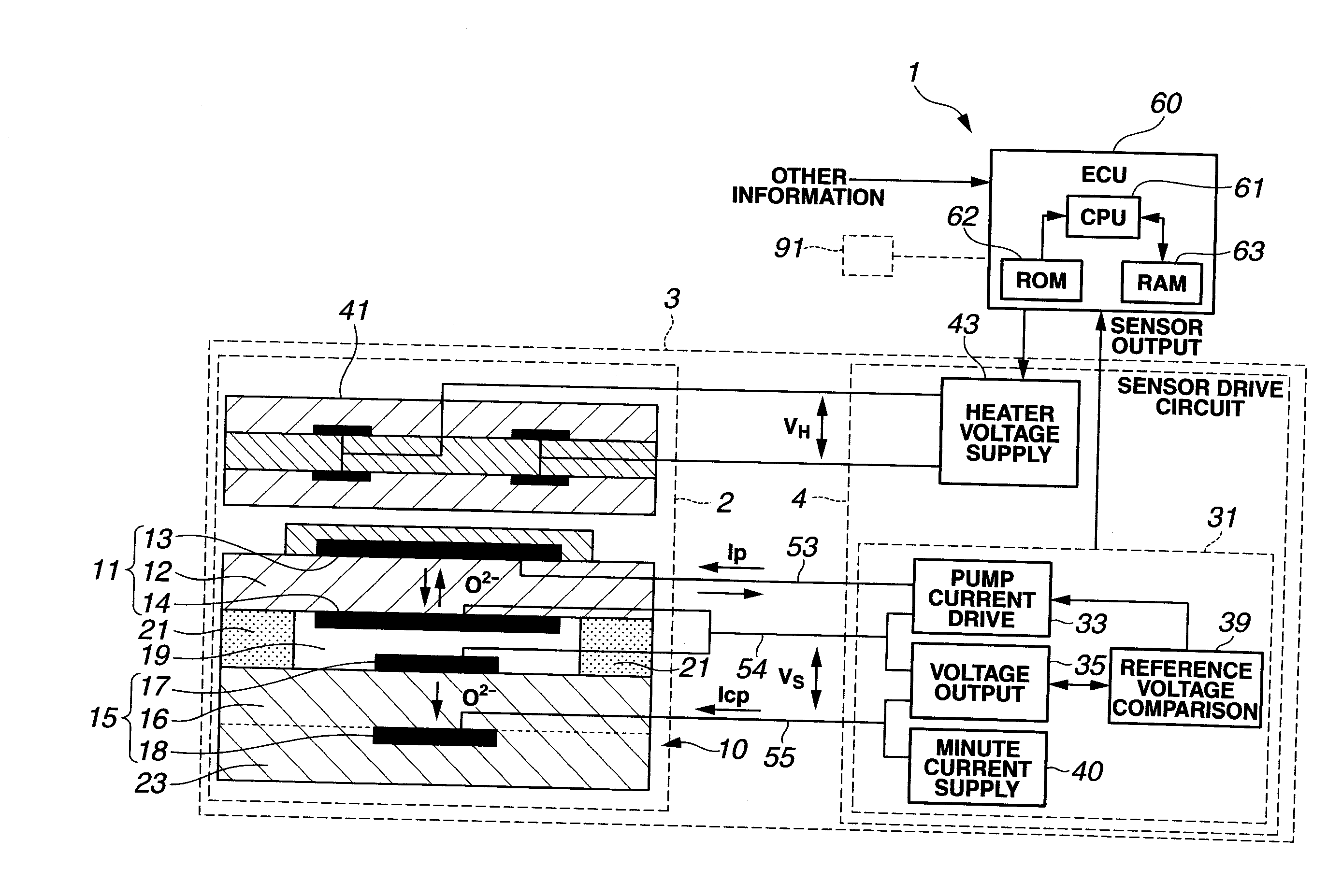
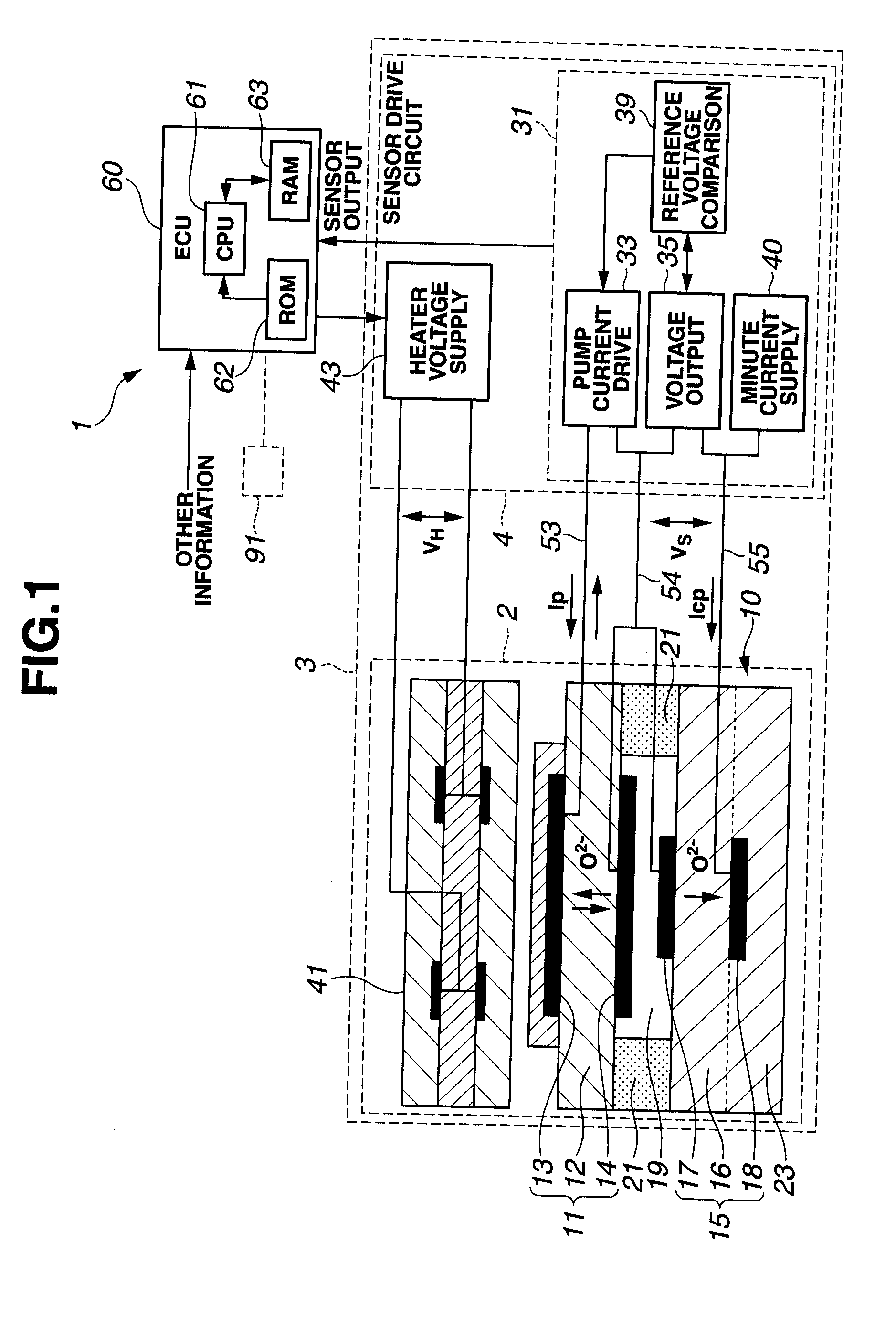
[0017]FIGS. 1˜5 show a gas sensor diagnosis or diagnostic process for determining whether a gas sensor is in an abnormal state or not, and a gas sensor system, according to the present invention. As shown in FIG. 1, the gas sensor system includes a gas sensor unit 3 and a gas sensor control unit or controller 1. In the example shown in FIG. 1, gas sensor unit 3 employs a wide-range (or full-range) air-fuel ratio sensing element 10 (hereinafter referred simply as sensing element 10) capable of sensing the oxygen concentration in a wide (or full) range of the air-fuel ratio from the rich region to the lean region across the theoretical air-fuel ratio. In this example, the gas sensor system is arranged to sense the concentration of oxygen contained in exhaust gases of an internal combustion engine for a vehicle, by gas sensor unit 3, and to use, or enable the use of, the sensed oxygen concentration for the control (such as feedback control) of the air-fuel ratio of the internal combust...

second embodiment

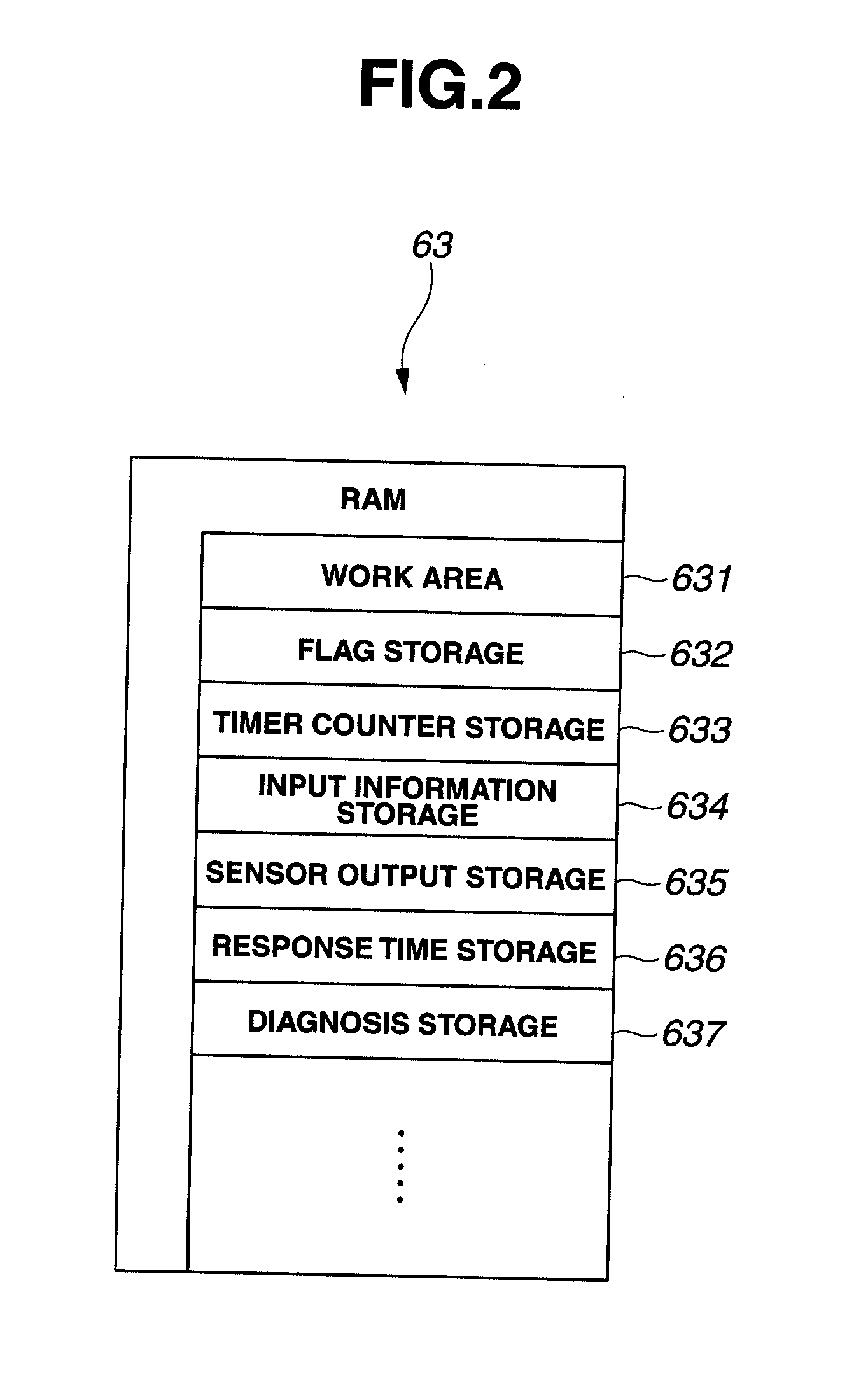
[0061]As described above, the abnormal state diagnostic process of the second embodiment is performed. CPU 61 of FIG. 1 is configured to obtain the engine speed of the internal combustion engine by referring to the input information storage area 634 at step S245 of the flowchart of FIG. 7. CPU 61 corresponds to an engine speed obtaining section. CPU 61 of FIG. 1 is configured to judge whether or not the sensor output value is stably outputted by judging whether or not sensing element 10 is activated at step S21 of FIG. 6. CPU 61 of FIG. 1 corresponds to a sensor output value judging section. CPU 61 of FIG. 1 is configured to accumulate the number that voltage Vs is continuously in the predetermined range by using the counter at step S225, step S230 and step S235 of the flowchart of FIG. 7 and step S23 of the flowchart of FIG. 6. CPU 61 is configured to judge whether or not the counter is equal to or greater than 40 at step S240 of the flowchart of FIG. 7, that is, to judge whether o...


PUM


Abstract

A gas sensor diagnostic method includes: a fuel supply detecting step of detecting an interruption of a fuel supply to the internal combustion engine, and a restart of the fuel supply after the interruption of the fuel supply; a response time period accumulating step of determining a response time period by accumulating a first time period that the sensor output value reaches from a first threshold value to a second threshold value after the detection of the interruption of the fuel supply, and a second time period that the sensor output value reaches from a third threshold value to a fourth threshold value after the detection of the restart of the fuel supply after the interruption of the fuel supply; and an abnormal state diagnosing section of determining an abnormal state of the gas sensor when the response time period is greater than a predetermined time period.

Description

BACKGROUND OF THE INVENTION[0001]This invention relates to an abnormal state diagnosis method for examining whether or not a gas sensor disposed in an exhaust passage of an internal combustion engine is in an abnormal state, and / or gas sensor control or diagnostic apparatus for such a gas sensor.[0002]A three-way catalyst is widely used in internal combustion engines for motor vehicles and other applications, to purify CO, HC and NOx contained in exhaust gas mixture. Furthermore, in order to improve the efficiency of the purification, there is provided a feedback air-fuel ratio control system including a gas sensor disposed in the exhaust passage of the engine, for sensing the oxygen concentration in the exhaust gases, and a controller for controlling the mixture ratio or air-fuel ratio toward the theoretical air-fuel ratio by regulating a fuel supply quantity, such as a fuel injection quantity, to the engine in accordance with the sensed oxygen concentration. Recently, the feedback...

Claims


Application Information

Patent Timeline
IPC IPC(8): F02D41/22F02D35/00F01N11/00
CPCF02D41/1456F02D41/1495F02D41/126G01N27/4175F02D41/123F02D2250/14
Inventor FUKAGAI, REINAIEDA, NORIKAZUTANAKA, MASAHIROINAGAKI, HIROSHITAKAMATSU, KUNIHIKOHIRATA, MASAKISUZUKI, TAKAHIRO
Owner NGK SPARK PLUG CO LTD
Why Eureka
Try Eureka