Multi-driver transducer having symmetrical magnetic circuit and symmetrical coil circuit

a transducer and magnetic circuit technology, applied in the direction of transducer details, electrical transducers, electrical apparatus, etc., can solve the problems of harmonic distortion and high total harmonic distortion of the transducer, and achieve the effect of super-high efficiency, great driving power and total harmonic distortion of the four-driver transducer

Inactive Publication Date: 2015-09-24
ZHANG FAN
View PDF4 Cites 15 Cited by
  • Summary
  • Abstract
  • Description
  • Claims
  • Application Information

AI Technical Summary

Benefits of technology

[0004]A first object of the present invention is to overcome the drawbacks in the prior art and a technical prejudice formed in the technical field of electroacoustics, and utilize two sets of symmetrical magnetic circuits and symmetrical coil circuits in the transducer or loudspeaker that has resistive load features or near-resistive load features in the technical solutions as disclosed by the inventor in CN200610020317.7, PCT / CN2008 / 072668, US2005 / 0099255A1, CN200510091936.0, CN200810169693.1, and PCT / CN2009 / 070507, etc. to constitute a transducer having a pair of mutually-repelling magnets and four drivers. Among the four sets of symmetrical magnetic circuits and symmetrical coil circuits in the transducer, every two sets of symmetrical magnetic circuits and symmetrical coil circuits can mutually offset the inductance of the coil circuits themselves in the transducer and back electromotive force acquired via induction, and thereby the total harmonic distortion of the four-driver transducer is improved unprecedentedly while great driving power and super-high efficiency are obtained in the transducer, wherein, the THD+N can be smaller than or equal to 3% and meet the Hi-Fi criterion for loudspeakers.

Problems solved by technology

The advantage of these technical solutions is that the transducer has high efficiency and strong driving power, but a drawback of them is that the transducer still has inductive load features and back electromotive force, resulting in high total harmonic distortion in the transducer, especially a woofer or subwoofer, wherein, at 1 W / 1 m, it is hard for the total harmonic distortion (THD+N) to meet the criterion specified in the Chinese national standard of smaller than or equal to 6%, and the total harmonic distortion often reaches as high as 10%43% or even higher.

Method used


Image

  • Multi-driver transducer having symmetrical magnetic circuit and symmetrical coil circuit
  • Multi-driver transducer having symmetrical magnetic circuit and symmetrical coil circuit
  • Multi-driver transducer having symmetrical magnetic circuit and symmetrical coil circuit

Examples


embodiment 1

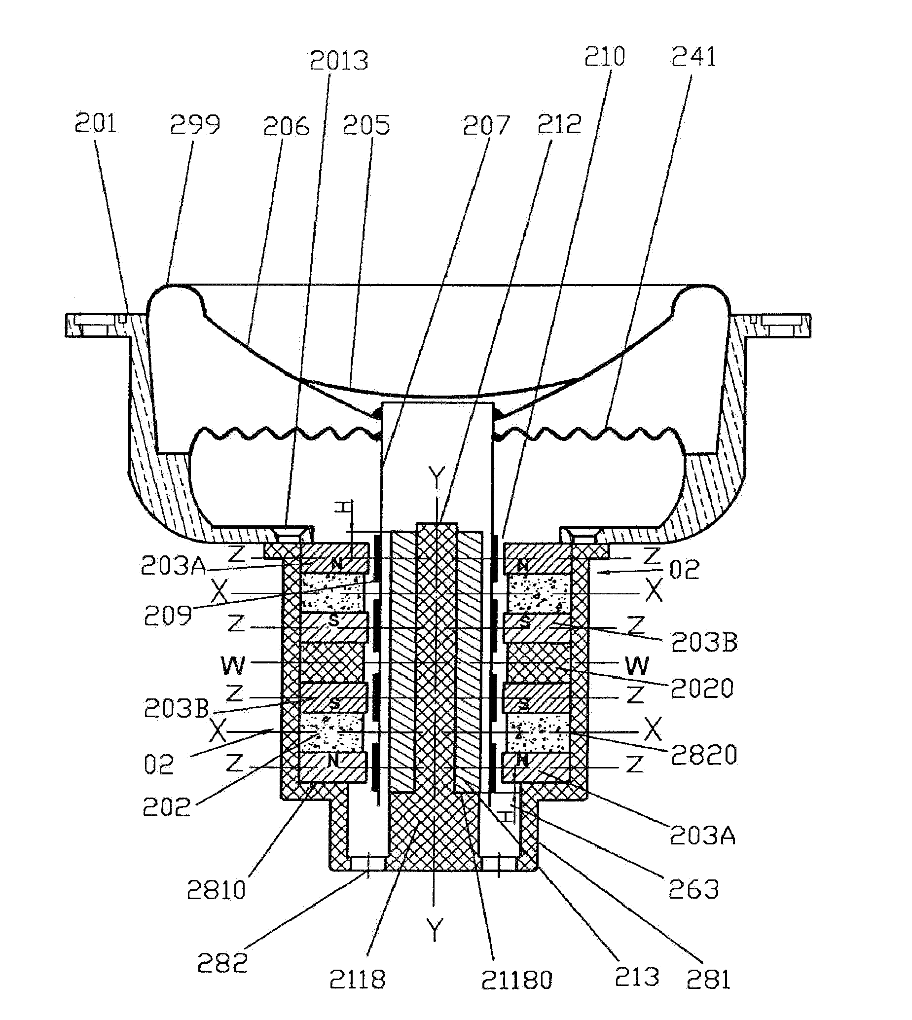
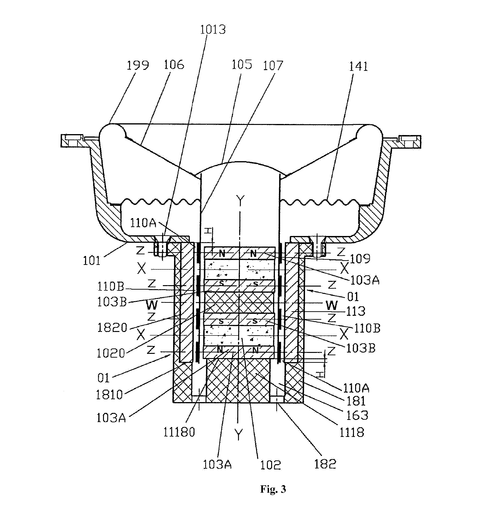
[0085]FIG. 3 shows a longitudinal sectional plan of Embodiment 1 of the inner magnet multi-driver transducer disclosed in the present invention.

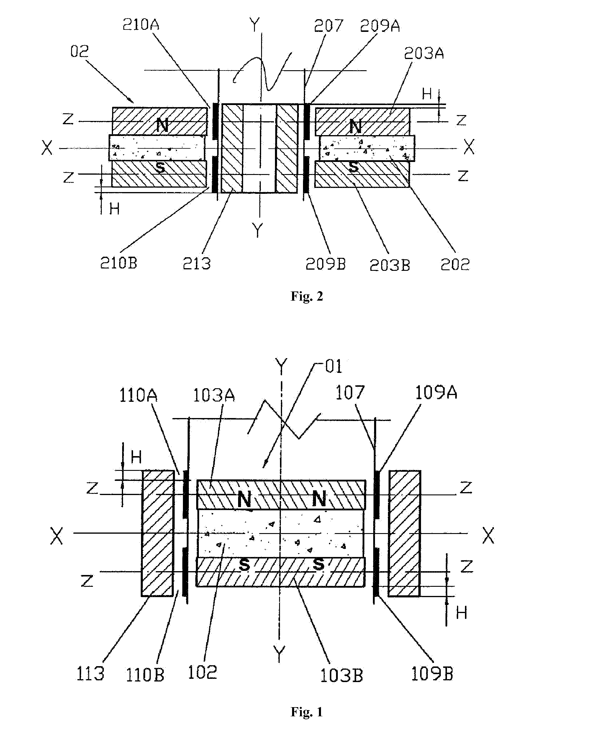
[0086]This is an embodiment of an inner magnetic four-driver loudspeaker having symmetrical magnetic circuits and symmetrical coil circuits. Upper pole plate 103A and lower pole plate 103B are coaxially mounted, have the same thickness and projected area, and match the permanent magnet 102; one or more uniform-thickness, uniformly distributed, and axially charged Nd—Fe-b magnets 102 bond the upper pole plate 103A and lower pole plate 103B into an integrated magnetic core. Thus, two identical sets of dual magnetic gap, dual coil, and inner magnet driver unit 01 are formed, and each set of dual magnetic gap, dual coil, and inner magnet transducer driver unit 01 have the same structure and working principle as the transducer driver unit described in the embodiment shown in FIG. 1. Hence these transducer driver unit will not be further detailed ...

embodiment 2

[0093]FIG. 4 shows a longitudinal sectional plan of Embodiment 2 of the inner magnet multi-driver transducer disclosed in the present invention.

[0094]This is an improved solution based on the embodiment shown in FIG. 3, and is applicable to a middle-diameter or large-diameter inner magnet multi-driver loudspeaker. In this embodiment, the upper pole plates 103A and lower pole plates 103B are four circular pole plates, and the permanent magnet 102 has an axial hole that matches the upper pole plates 103A and lower pole plates 103B. A through-hole or bolt though-hole is arranged at the central axis of the inwardly protruding platform 1118 of the bracket. When the two sets of dual magnetic gap, dual coil, and inner magnet driver unit 01 shown in FIG. 1 are assembled, a fastener 1710 made of a non-magnetic material (e.g., a 1Cr18Ni9Ti stainless steel bolt) is inserted from top to bottom through all mating axial holes of a washer 172 made of a non-magnetic material, the upper pole plate 1...

embodiment 3

[0099]FIG. 5 shows a longitudinal sectional plan of Embodiment 3 of the inner magnet multi-driver transducer disclosed in the present invention.

[0100]This is a variant of Embodiment 2 shown in FIG. 4: one tubular magnetic yoke 113 is changed to two separate tubular magnetic yokes 113 that are coaxial with each other and in the same height. In addition, an annular partition 1021 matching the two separate tubular magnetic yokes 113 made of a non-magnetic material is added to bond the two tubular magnetic yokes 113 into an integral assembly, . . . . In other aspects, the structure and working principle of this embodiment are identical to those of the embodiment shown in FIG. 4, and will not be further detailed here.

[0101]FIG. 6 shows a longitudinal sectional plan of Embodiment 1 of the outer magnet multi-driver transducer disclosed in the present invention.

[0102]This is an embodiment of an outer magnet four-driver loudspeaker having symmetrical magnetic circuits and symmetrical coil ci...


PUM


Abstract

A multi-driver transducer having symmetrical magnetic circuits and symmetrical coil circuits, wherein one or more pieces of circular or annular partitions made of a non-magnetic material are used to bond two or more sets of dual magnetic gap and dual coil driver units (01 or 02) into one integrated magnetic core. Four or more coaxial isodiametric annular magnetic gaps are formed between the inner circumferential face or outer circumferential face of one or two tubular magnetic yokes embedded in an open-end tubular thin wall of the bracket and the vertical circumferential face of an upper pole plate and a lower pole plate of the magnetic core, four or more coaxial and isodiametric coils are inserted in the four or more coaxial and isodiametric annular magnetic gaps, and the winding direction, connection manner, and necessary technical features of the coils are governed; thus, the multi-driver transducer having one or more pairs of mutually-repelling magnets, symmetrical magnetic circuits, and symmetrical coil circuits is constituted. Back electromotive force and inductance acquired via induction by the transducer during the working process are mutually offset. The transducer has resistive load features or near-resistive load features, and has super-high sensitivity, high resolution, and high-fidelity quality.

Description

FIELD OF THE INVENTION[0001]The present invention relates to a multi-driver transducer, in particular to a multi-driver transducer having mutually-repelling magnets, symmetrical magnetic circuits, and symmetrical coil circuits, and belongs to the electrical field of electroacoustic transducers and electromechanical transducers.BACKGROUND OF THE INVENTION[0002]A main-stream conventional electroacoustic transducer or electromechanical transducer only has one magnetic gap and one coil, which constitute a moving-coil type driver. A multi-driver transducer having mutually-repelling magnets has two or more magnetic gaps and two or more coils, which constitute two or more moving-coil type multi-driver transducers.[0003]Multi-driver transducers having mutually-repelling magnets belong to an existing technique. For example, in the technical solutions proposed by the inventor in PCT / CN98 / 00306, PCT / CN2008 / 072668, PCT / CN2009 / 070507, CN99114781.2, and TW88109796, etc., wherein moving-coil type ...

Claims


Application Information

Patent Timeline
Patent Type & Authority Applications(United States)
IPC IPC(8): H04R9/06H04R9/02H04R9/04
CPCH04R9/063H04R9/025H04R9/043H04R9/04H04R2209/041
Inventor ZHANG, FAN
Owner ZHANG FAN
Why Eureka
Try Eureka