Periodic disturbance automatic suppression device

a technology of automatic suppression and periodic disturbance, which is applied in the direction of electric generator control, dynamo-electric converter control, dynamo-electric gear control, etc., can solve the problems of increasing the settling time to the end of suppression, control instability, and difficulty in obtaining accurate identification models, so as to improve the robustness of identification models, improve the performance of suppressing periodic disturbance, and improve the accuracy of system identification

Inactive Publication Date: 2015-11-12
MEIDENSHA ELECTRIC MFG CO LTD
View PDF1 Cites 7 Cited by
  • Summary
  • Abstract
  • Description
  • Claims
  • Application Information

AI Technical Summary

Benefits of technology

[0013]In the control based on the periodic disturbance observer, the core basis of the control influencing the control performance is the accuracy with respect to true value(s) of the system identification model P̂n. To improve the performance of suppressing the periodic disturbance, it is required to improve the accuracy of the system identification. However, it is difficult to obtain an accurate identification model, and it is necessary t...

Problems solved by technology

However, it is difficult to obtain an accurate identification model, and it is necessary to take account of long term variation of the plant due to aging or other factors, and short term variation due to unexpected sudden system variation.
Error in the identification mo...

Method used


Image

  • Periodic disturbance automatic suppression device
  • Periodic disturbance automatic suppression device
  • Periodic disturbance automatic suppression device

Examples


first embodiment

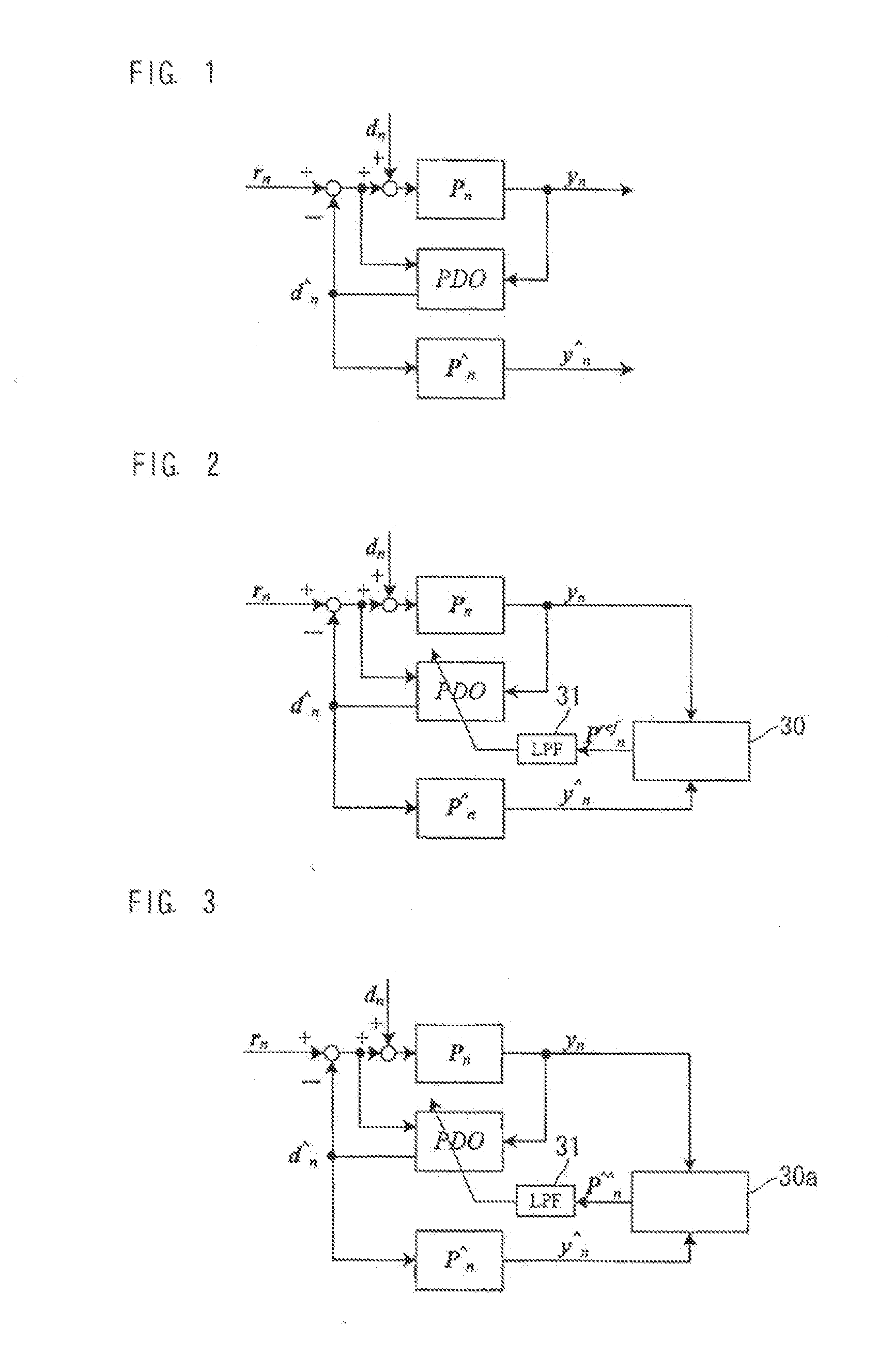
[0028]FIG. 1 shows a periodic disturbance observer control structure according to the present invention. In FIG. 1, following symbols are used.

Pn: plant (controlled object), d̂n: estimated periodic disturbance (system identification model),

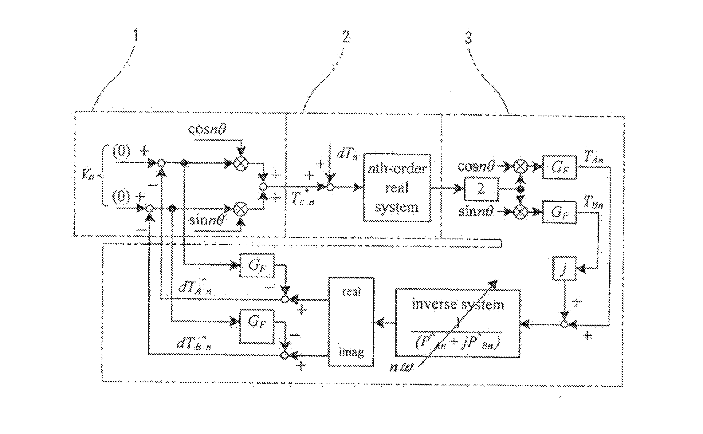
yn: controlled object output (corresponding to TAn, TBn in FIG. 6),

rn: nth order control command, dn: nth order disturbance,

d̂n·t: nth order compensation command at instant t (corresponding to dTÂn, dTB̂n in FIG. 6),

P̂n: identification model, ŷn: estimated plant output of the identification model P̂n when d̂n, is a disturbance,

PDO: periodic disturbance observer, yn·t: nth order output at instant t. Quantities in the s region are represented by instant t after comma of subscript.

[0029]Equations of state are expressed at an instant t1 by following expressions (2) and (3). It is assumed that the command or command value is constant while t=t0˜tn, and the command is a steady-state value having no periodicity expressed as rn=0 [n>0]. Each quantity is...

third embodiment

[0039]FIG. 4 is a control block diagram for the periodic disturbance observer PDO according to the There are provided a memory function of memory function section 32 and a switch SW. In the other points, the system of FIG. 4 is constructed in the same manner as the system of FIG. 2.

[0040]The memory function section 32 stores table data for referring to a rotation frequency nω of the plant and the system identification error prefn. As expressed by an equation (10), a corrected identification model P̂n is determined by multiplying the equation (9), by a memory output of a rotation vector Pnmem, and this identification model P̂n is used for the control in the periodic disturbance observer PDO.

P̂n=prefn·P̂n·Pnmem  (10)

[0041]As to the timing of storing the corrected identification mode P̂n in the memory function section 32, the corrected identification model P̂n is stored at a switching timing of the switch SW which is switched at a timing when an operation of correcting the identificat...

fourth embodiment

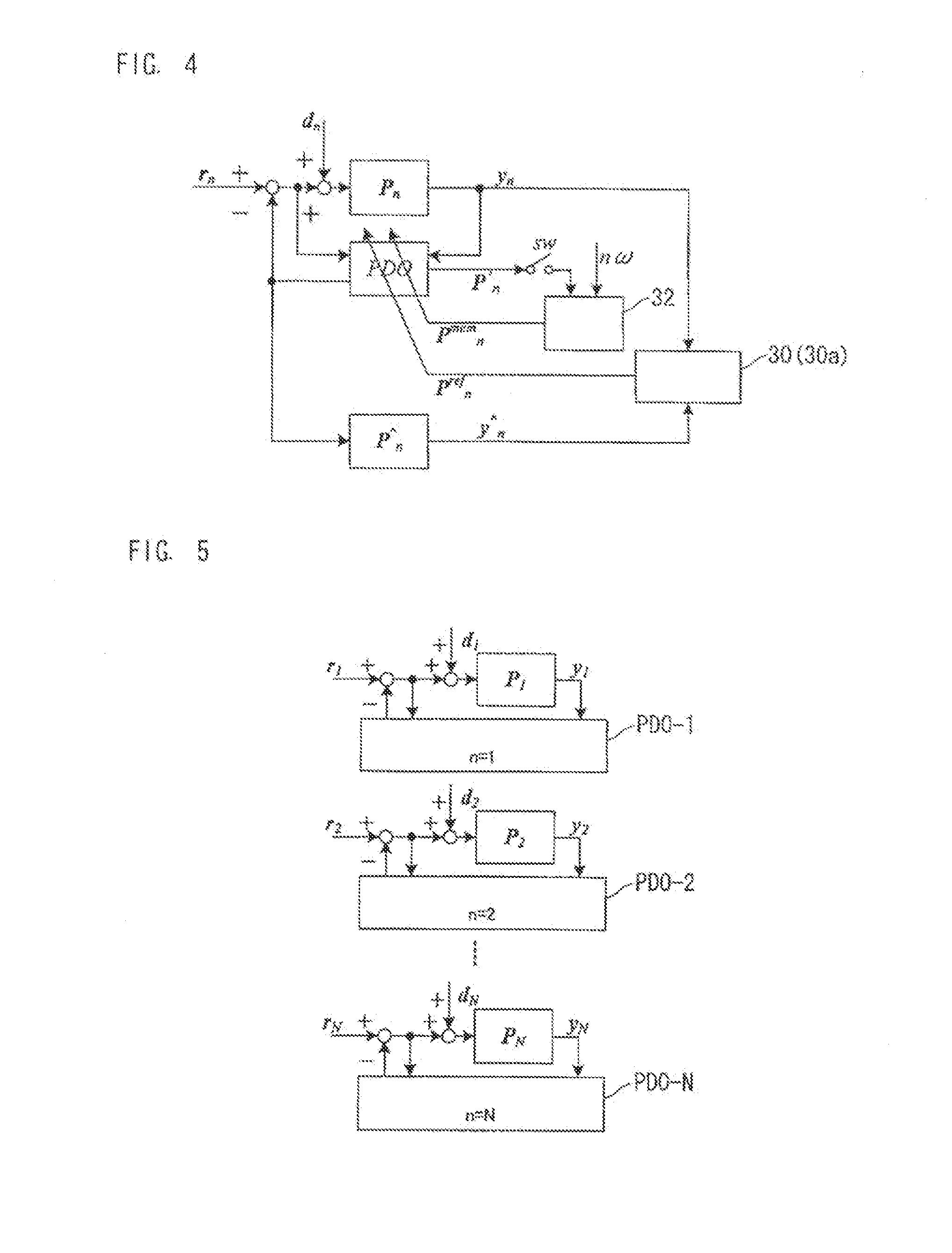
[0043]In the preceding embodiments, the apparatus is arranged to be able to estimate the identification model error and correct the identification model at a predetermined frequency. In a fourth embodiment shown in FIG. 5, the apparatus includes a control system provided for each of the orders of suppression, and the control systems provided, respectively, for the orders are arranged in parallel with one another so as to form parallel and simultaneous arrangement. In other words, the apparatus includes N units or sections each including a periodic disturbance observer PDO provided with a model error correction shown in FIGS. 1˜4, for estimating an identification model error with respect to an nth order periodic disturbance component to be estimated. Estimated periodic disturbances d̂n−1˜d̂n−N obtained by the correction of the system identification model with the estimated errors are delivered to the torque ripple compensation calculating section 1 (shown in FIG. 6).

[0044]As explaine...


PUM


Abstract

In suppression of torque ripple with a periodic disturbance observer, adjustment of a gain portion is determined sequentially during monitoring operation of monitoring an operating condition. Therefore, many adjusting parameters are involved and achievement of correction is dependent on the skill of a person in charge of adjustment or design.
The periodic disturbance observer is provided with a model correcting means or section which calculates an error of an identification model by using a time difference quantity by an output of the periodic disturbance observer and a sensed value of a plant and corrects the identification model with the error of the identification model. Finally, the system performs the torque ripple suppression control with an accurately estimated periodic disturbance.

Description

TECHNICAL FIELD[0001]The present invention relates to an automatic periodic disturbance suppression apparatus or device for automatically suppressing torque ripple in a rotating electric machine such as motor, and more specifically to an automatic periodic disturbance suppression apparatus adapted to correct an identification model of a periodic disturbance observer as required during a suppression control.BACKGROUND ART[0002]Control for suppressing occurrence of periodic disturbance is used in various controls such as electric power system control in receiving and transforming facilities, positioning control with robot, shaft torque resonance suppression in dynamometer system, and vibration suppression of motor housing (relating to riding comfort of a vehicle such as electric vehicle and elevator). In these applications, there is a demand for suppressing periodic disturbance accurately.[0003]A motor, for example, produces torque ripple in principle, and thereby causes various probl...

Claims


Application Information

Patent Timeline
IPC IPC(8): H02P21/13
CPCH02P21/13G05B19/19G05B2219/41132
Inventor YAMAGUCHI, TAKASHITADANO, YUGO
Owner MEIDENSHA ELECTRIC MFG CO LTD
Why Eureka
Try Eureka