Gas valve

a gas valve and valve body technology, applied in the field of gas valves, can solve the problems of flat contact surface wear, gas valve malfunctions, and relatively quick wear of sealing seats in the form of knife edges

Inactive Publication Date: 2016-03-24
ROBERT BOSCH GMBH
View PDF7 Cites 0 Cited by
  • Summary
  • Abstract
  • Description
  • Claims
  • Application Information

AI Technical Summary

Benefits of technology

[0004]It is the underlying object of the invention to pr...

Problems solved by technology

However, the disadvantage is that the sealing seat in the form of a knife edge can wear relatively quickly owing to the knife-edge design and, as a ...

Method used


Image

  • Gas valve
  • Gas valve
  • Gas valve

Examples


Embodiment Construction

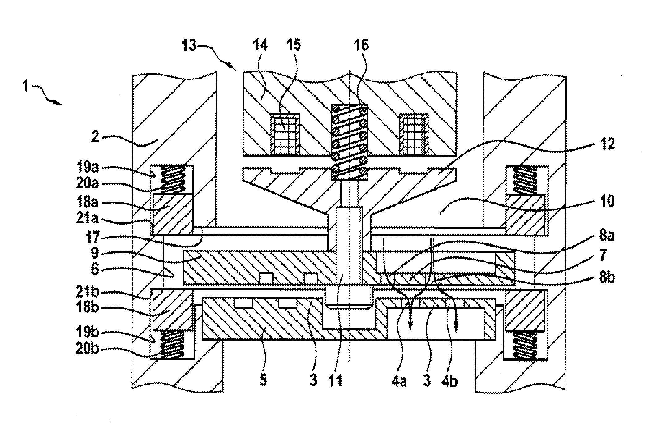
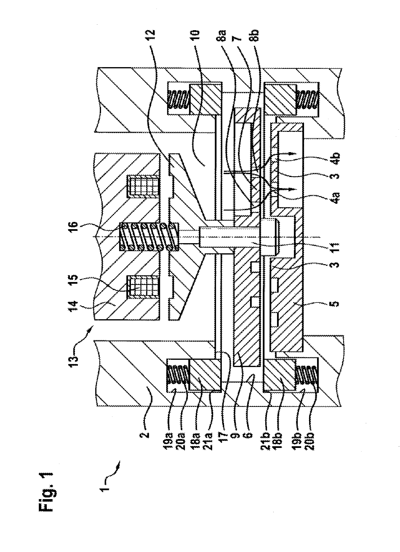
[0022]The gas valve 1 shown in FIG. 1 is designed as a gas inlet valve, by means of which a gaseous fuel is fed directly or indirectly to a combustion chamber of an internal combustion engine. In this case, the gas valve can be installed on an intake section of the internal combustion engine and can inject the gaseous fuel centrally into the intake section. However, it is also possible for the gas valve 1 to be installed in an intake branch of the intake section, wherein the intake branch is the intake duct leading to an inlet valve directly adjoining a combustion chamber of the internal combustion engine. In the context of the invention, it is furthermore also possible for the gas valve 1 to be installed in a cylinder head of the internal combustion engine and to be in direct contact on the outlet side with the combustion chamber, bypassing the intake section and the intake duct. By means of the gas valve 1, gaseous fuel is introduced into the combustion chamber, is burnt there wit...


PUM


Abstract

A gas valve 1, in particular a dosing valve for a gaseous medium, having a valve seat body 3, which is arranged on a valve housing 2, and a closing body 7, which can perform a stroke motion relative to the valve seat body 3 and to an opening stroke stop 17 interacting with the valve housing 2. According to the invention, a gas valve 1 is provided which is improved as regards its durability. This is achieved by virtue of the fact that the gas valve 1 has an impact body which reduces the impact speed and/or impact energy of the closing body 7 on the valve seat body 3 and/or on the opening stroke stop 17.

Description

BACKGROUND OF THE INVENTION[0001]The invention relates to a gas valve, in particular a dosing valve for a gaseous medium, having a valve seat body, which is arranged on a valve housing, and a closing body, which can perform a stroke motion relative to the valve seat body and to an opening stroke stop interacting with the valve housing.[0002]A gas valve of this kind is known from DE 10 2009 002 836 A1. This gas valve is a dosing valve for a gaseous medium, which has a valve chamber arranged in a valve housing and having at least two chamber openings, of which a first chamber opening is surrounded in an annular manner by a valve seat, and a closing body, which is arranged in the valve chamber and on which a sealing seat that can be placed on the valve seat and raised from the valve seat is formed. The sealing seat is in the form of a knife edge and thereby ensures leaktight seating upon initial commissioning of the gas valve by means of a sealing impact into the closing body. However,...

Claims


Application Information

Patent Timeline
IPC IPC(8): F02M63/00F02M35/10F16K3/02F16K47/04
CPCF02M63/0031F16K3/0218F02M63/0077F02M35/10216F16K47/04F02M21/0239F02M35/10255F16K31/0689Y02T10/30
Inventor MINIXHOFER, CLAUSMITTER, ROLANDHAINBERGER, MARTIN
Owner ROBERT BOSCH GMBH
Why Eureka
Try Eureka