Combustion device for an outdoor flame heater

a combustion device and flame heater technology, applied in the field of outdoor flame heaters, can solve problems such as maintenance difficulties, and achieve the effects of improving combustion efficiency and heating effect, convenient maintenance, and increasing safety

Inactive Publication Date: 2016-05-12
LIANG HSIN LIEN
View PDF20 Cites 14 Cited by
  • Summary
  • Abstract
  • Description
  • Claims
  • Application Information

AI Technical Summary

Benefits of technology

[0010]It is a primary object of the present invention to provide an improved combustion device for an outdoor flame heater that provides a combustion device to enhance the combustion efficiency and the heating effects for outdoor placement, and to have a structure for easy maintenance and more safety.

Problems solved by technology

Moreover, the ceramic burner 142 is arranged inside the base 14, which is difficult for maintenance.

Method used


Image

  • Combustion device for an outdoor flame heater
  • Combustion device for an outdoor flame heater
  • Combustion device for an outdoor flame heater

Examples


Embodiment Construction

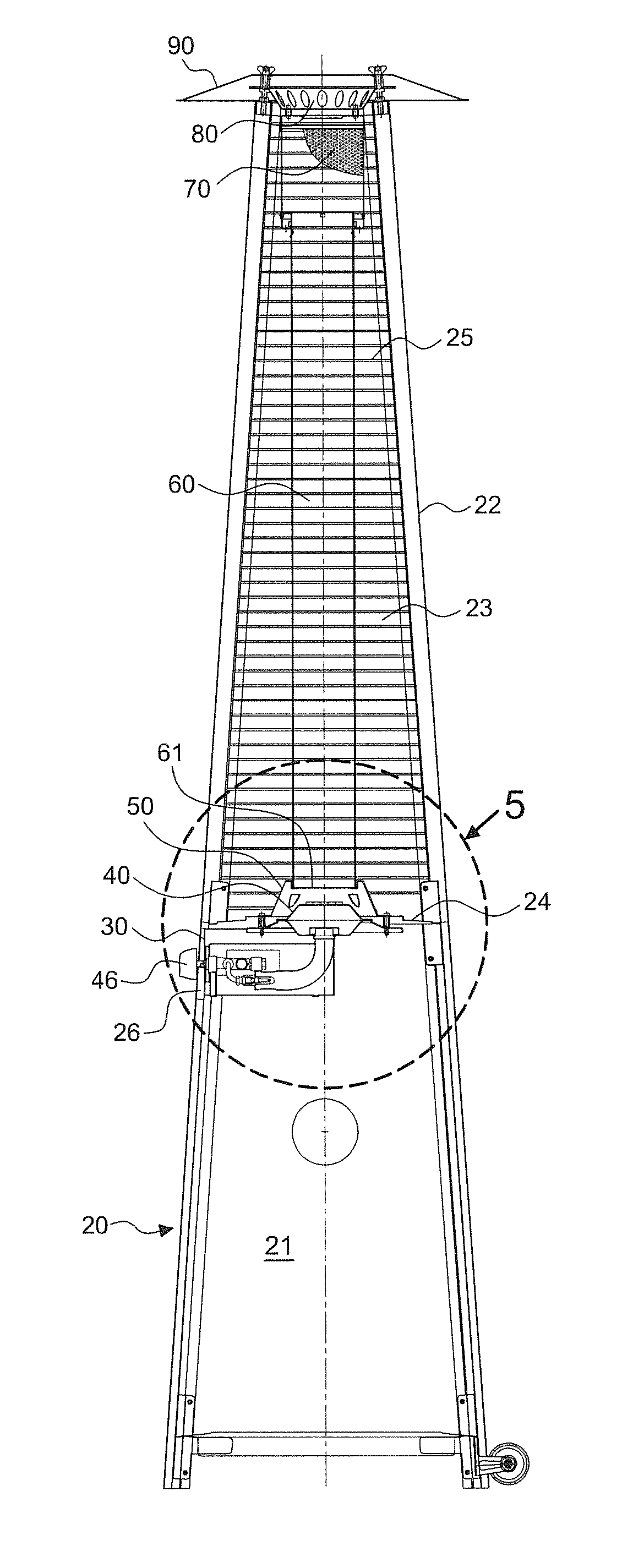
[0021]With reference to FIGS. 2-8, in a preferred embodiment, the present invention includes a housing 20, a base 30, a burner 40, a plurality of support members 22, a glass tube 60, and a cover 50.

[0022]The housing 20 has an inside space 21 for installing a gas barrel (not shown). The base 30 is mounted on the housing 20 and has a gas intake tube 44 and a gas control switch 45. The burner 40 is mounted on the base 30 and has a lighting device 47 arranged at a side edge thereof. The support members 22 have a bottom end fixed on the housing 20 to define a mounted space 23 therein. The glass tube 60 is disposed in the mounted space 23; the glass tube 60 may be made of quartz glass which is heat-resistant. In this embodiment, the present invention further includes a plurality of protective wire meshes 25 fixed between the support members 22 to avoid contacting the glass tube 60 with high-temperature.

[0023]The burner 40 includes a top surface extending to define a gas distribution room ...


PUM


Abstract

A combustion device for outdoor flame heaters includes an improved structure of a burner disposed below a glass tube thereof. The burner has a gas distribution room therein and a plurality of flame holes at a top surface thereof communicating with the gas distribution room and directed towards the glass tube. The flame holes have a diameter which is at least 10 mm for the flame to be in red and yellow, and a piece of metal wire mesh with a sieve size between 20-30 mesh abuts thereto from under in the gas distribution room, so as to construct a structure with a relatively greater diameter above and a relatively lesser diameter below for the flame to be emitted from the glass tube at an appropriate height by chimney effect to enhance the heating effects.

Description

[0001]This patent application is a continuation-in-part of Ser. No. 13 / 860,683 filed on Apr. 11, 2013, currently pending.BACKGROUND OF THE INVENTION[0002]1. Field of the Invention[0003]The invention relates to an outdoor flame heater, particularly to one that has an improved burner disposed below a glass tube to enhance combustion efficiency with easy maintenance and more safety.[0004]2. Description of the Related Art[0005]With reference to FIGS. 1A-1C, the US Patent Publication No. 2010 / 0236544 A1 discloses an outdoor flame heater 100 including a bottom housing 10 composed of a set of four lower support members 11, a set of four panels 12, and other relative members for installing a gas barrel (not shown); a control box 13 releasing a flame F to a gas flame outlet 141 of a base 14 on a top of control box 13; a set of four upper support members 15 together with a plurality of protection guards 16 forming a space for installing a glass tube 17; and a reflector 19 mounted onto a dampe...

Claims


Application Information

Patent Timeline
Patent Type & Authority Applications(United States)
IPC IPC(8): F24H3/00F23D14/22F24C15/06
CPCF24H3/006F23D14/22F24C15/06F23D14/02F23D14/82F24C1/12F24H3/0417F24H9/0068F24H9/0073
Inventor LIANG, HSIN-LIEN
Owner LIANG HSIN LIEN
Why Eureka
Try Eureka