Electroacoustic transducer

a transducer and electroacoustic technology, applied in the field of electroacoustic transducers, can solve the problems of low sound quality, achieve the effect of improving the electroacoustic conversion function characteristics, improving the sound quality, and improving the sound quality

Active Publication Date: 2016-06-02
TAIYO YUDEN KK
View PDF4 Cites 8 Cited by
  • Summary
  • Abstract
  • Description
  • Claims
  • Application Information

AI Technical Summary

Benefits of technology

[0006]In recent years, there is a demand for higher sound quality in the field of earphones, headphones, and other acoustic devices. Accordingly, improving their electroacoustic conversion function characteristics is an absolute must for piezoelectric sounding bodies. When music is played, etc., for example, sibilant vocal sounds appearing in the high-frequency band may lead to lower sound quality. What is required, in this case, is electroacoustic conversion function with high-frequency characteristics capable of reducing sound pressure peaks of the sibilant sounds.
[0007]In light of the aforementioned situations, an object of the present invention is to provide an electroacoustic transducer offering excellent high-frequency characteristics.
[0013]With the aforementioned electroacoustic transducer, the periphery of the vibration plate is supported by the support member in multiple areas. This way, more vibration of the periphery of the vibration plate is permitted when the piezoelectric element is driven, compared to when the entire periphery of the vibration plate is fixed to the support member, and desired high-frequency characteristics can be achieved as a result.
[0019]With the aforementioned electroacoustic transducer, the periphery of the vibration plate is supported by the support member via the elastically deformable adhesive layer. This way, more vibration of the periphery of the vibration plate is permitted when the piezoelectric element is driven, compared to when the entire periphery of the vibration plate is firmly fixed to the support member, and desired high-frequency characteristics can be achieved as a result.
[0020]As explained above, according to the present invention, an electroacoustic transducer offering excellent high-frequency characteristics can be provided.

Problems solved by technology

When music is played, etc., for example, sibilant vocal sounds appearing in the high-frequency band may lead to lower sound quality.

Method used


Image

  • Electroacoustic transducer
  • Electroacoustic transducer
  • Electroacoustic transducer

Examples


first embodiment

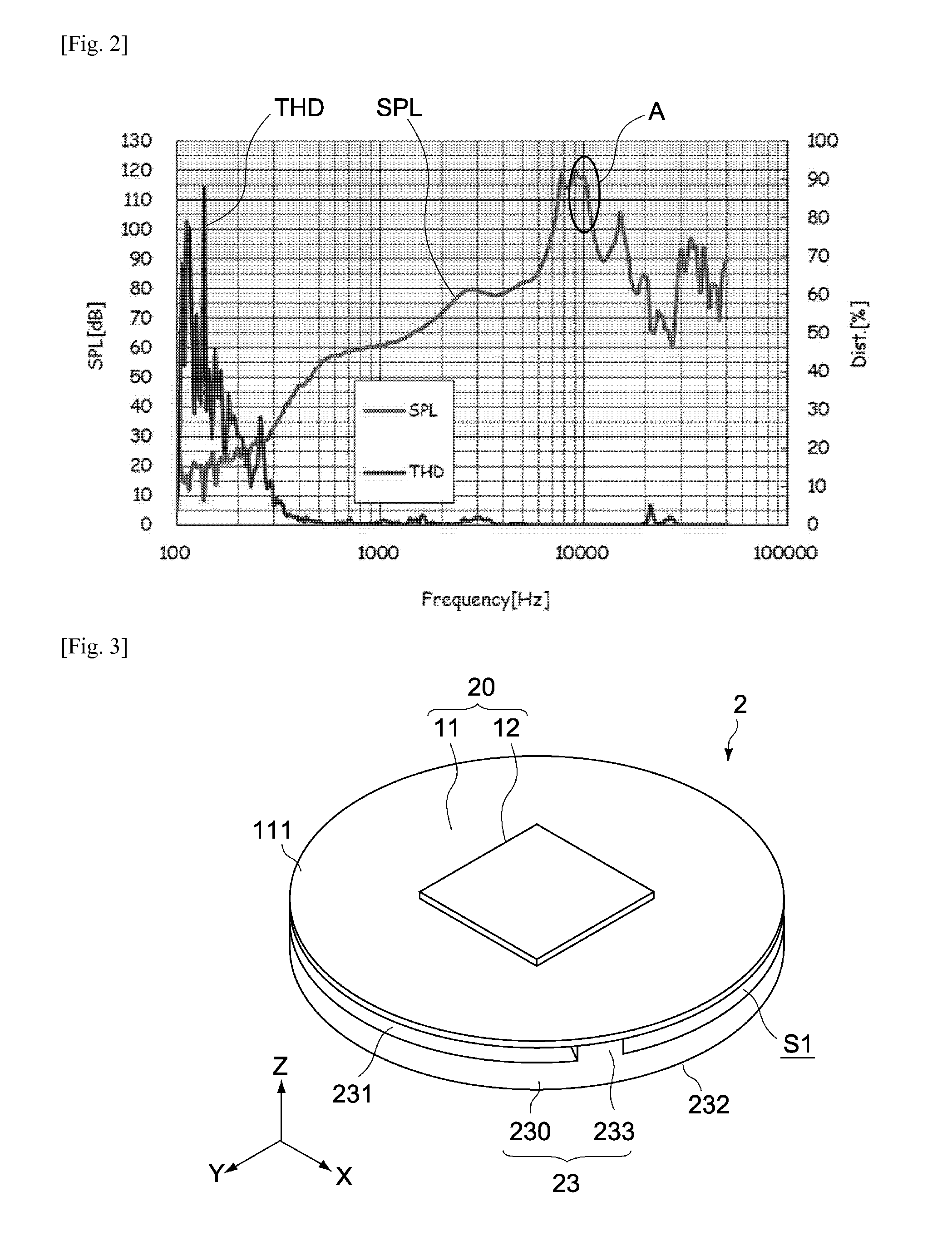
[0068]FIG. 3 is a general perspective view of a speaker unit pertaining to the first embodiment of the present invention, while FIG. 4 is an exploded perspective view of the same.

[0069]A speaker unit 2 in this embodiment has a piezoelectric speaker 20 and support member 23. The speaker unit 2 is housed inside a housing not illustrated here, to constitute an electroacoustic transducer for an earphone, headphone, etc.

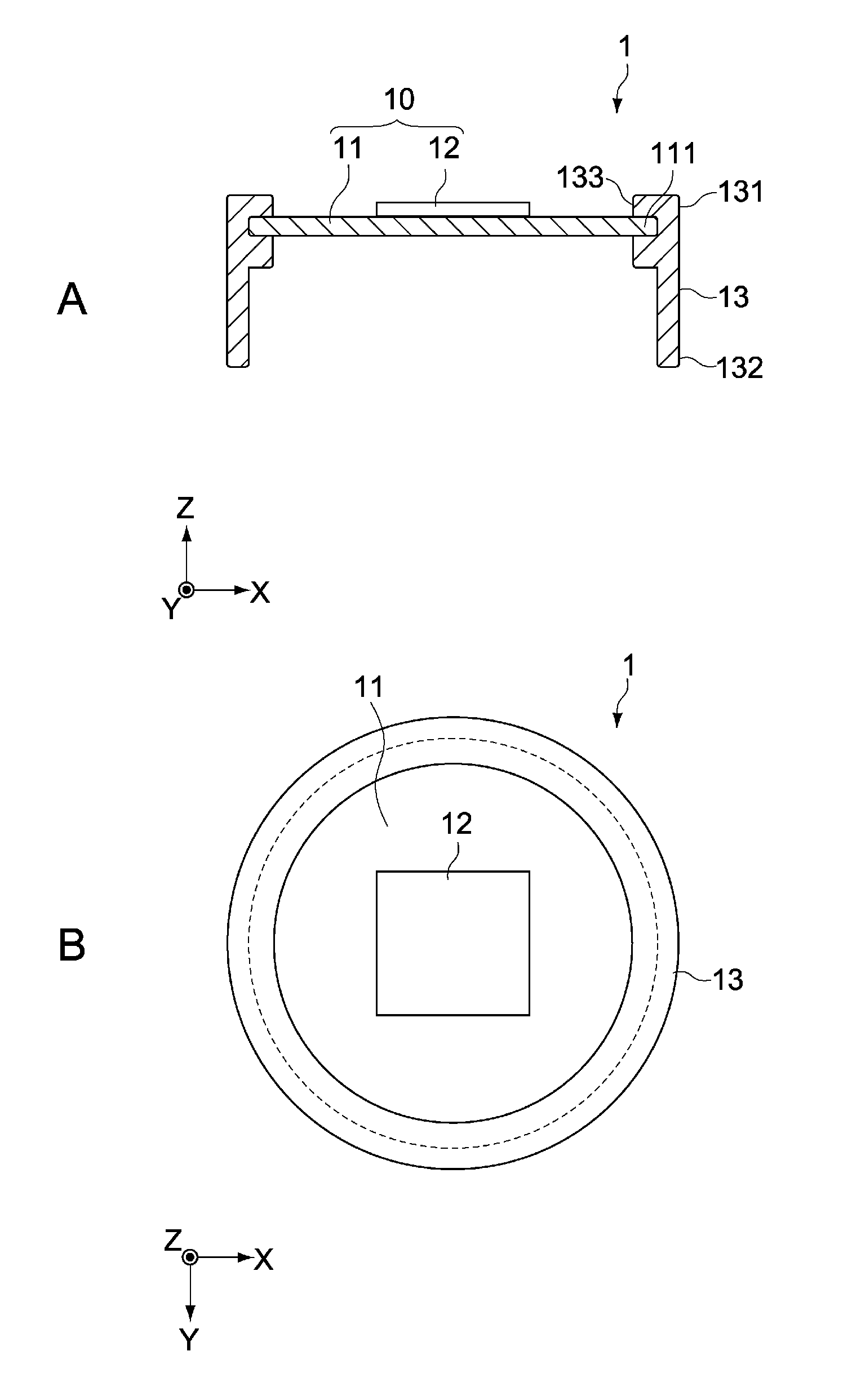
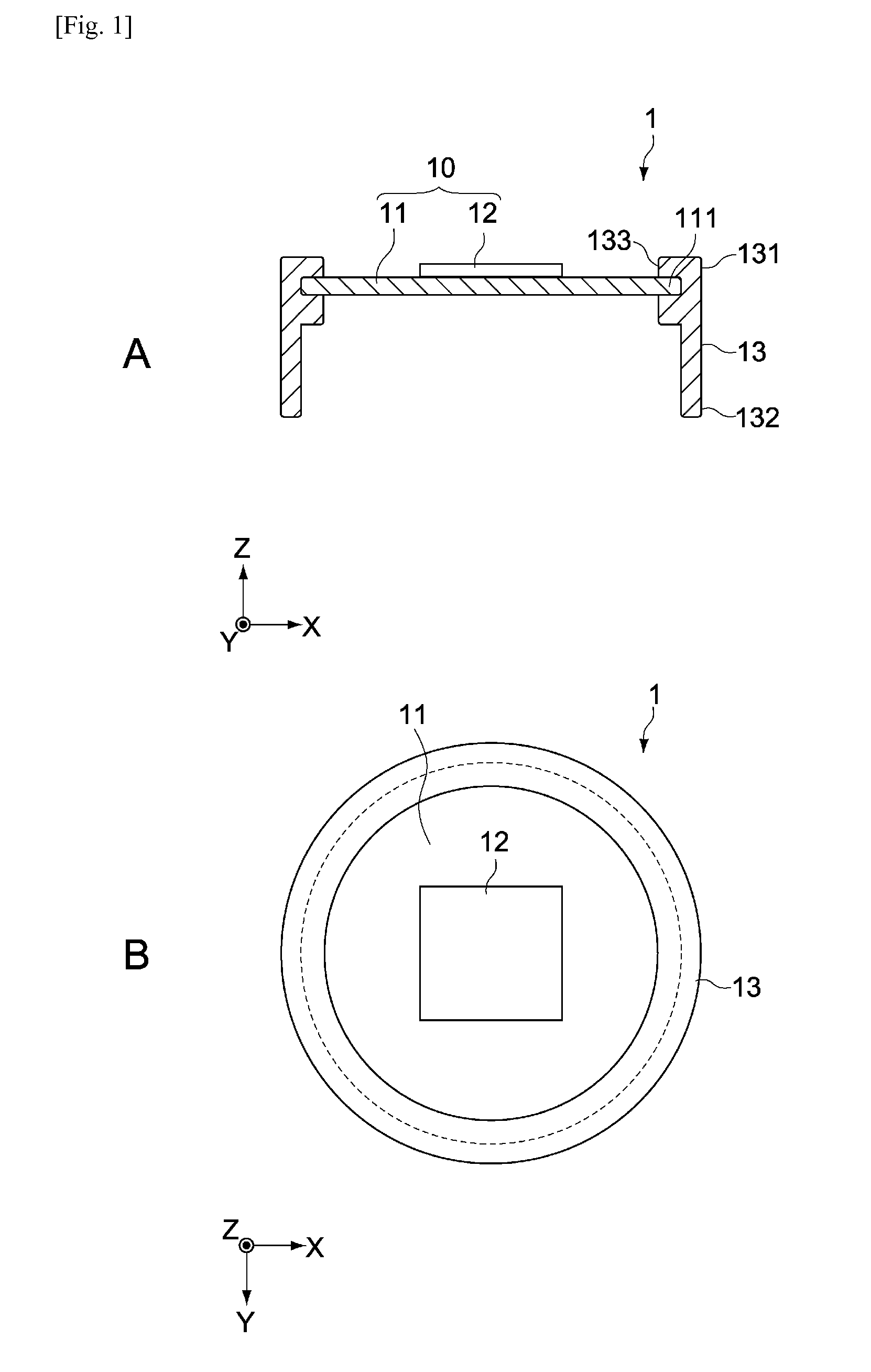
[0070]The piezoelectric speaker 20 has a vibration plate 11 and piezoelectric element 12. The vibration plate 11 and piezoelectric element 12 are constitutionally identical to the vibration plate 11 and piezoelectric element 12 of the electroacoustic transducer 1 pertaining to the aforementioned reference example and therefore not explained here.

[0071]The support member 23 supports the vibration plate 11 in multiple areas of its periphery 111. The support member 23 may be constituted by a part of the housing or by a member independent of the housing.

[0072]In this embodime...

second embodiment

[0085]FIG. 7 is a schematic lateral section view showing the constitution of a speaker unit 3 pertaining to the second embodiment of the present invention. Constitutions different from those of the first embodiment are primarily explained below, and the same constitutions as in the first embodiment are not explained or explained briefly using the same symbols.

[0086]The speaker unit 3 in this embodiment has a piezoelectric speaker 20 and support member 33.

[0087]The speaker unit 3 is housed inside a housing not illustrated here, to constitute an electroacoustic transducer for an earphone, headphone, etc.

[0088]In this embodiment, the support member 33 elastically supports the periphery 111 of the vibration plate 11 all around. The support member 33 may be constituted by a part of the housing or by a member independent of the housing.

[0089]The support member 33 has an annular body 330, and a ring-shaped convex 333 that supports the periphery 111 of the vibration plate 11. The support me...

third embodiment

[0100]A and B in FIG. 10 are a schematic lateral section view and plan view, respectively, showing the constitution of a speaker unit 4 pertaining to the third embodiment of the present invention. Constitutions different from those of the first embodiment are primarily explained below, and the same constitutions as in the first embodiment are not explained or explained briefly using the same symbols.

[0101]The speaker unit 4 in this embodiment has a piezoelectric speaker 20 and support member 43.

[0102]The speaker unit 4 is housed inside a housing not illustrated here, to constitute an electroacoustic transducer for an earphone, headphone, etc.

[0103]In this embodiment, the support member 43 supports the vibration plate 11 in multiple areas of its periphery 111. The support member 43 may be constituted by a part of the housing or by a member independent of the housing.

[0104]The support member 43 has an annular body 430, and multiple projections 433 to support the periphery 111 of the v...


PUM


Abstract

In an embodiment, an electroacoustic transducer has a piezoelectric speaker 20, housing, and support member 23. The piezoelectric speaker 20 has a vibration plate 11 with a periphery 111, and a piezoelectric element 12 joined to the vibration plate 11. The housing houses the piezoelectric speaker 20. The support member 23 is constituted by a part of the housing or by a separate member, and supports the vibration plate 11 in multiple areas along the periphery 111. The electroacoustic transducer can offer excellent high-frequency characteristics.

Description

BACKGROUND[0001]1. Field of the Invention[0002]The present invention relates to an electroacoustic transducer that can be applied to earphones, headphones, mobile information terminals, etc., for example.[0003]2. Description of the Related Art[0004]Piezoelectric sounding bodies are widely used as simple means for electroacoustic conversion, where popular applications include earphones, headphones, and other acoustic devices as well as speakers for mobile information terminals, etc., for example. Piezoelectric sounding bodies are typically constituted by a vibration plate and a piezoelectric element attached to it (refer to Patent Literature 1, for example).[0005][Patent Literature 1] Japanese Patent Laid-open No. 2013-150305SUMMARY[0006]In recent years, there is a demand for higher sound quality in the field of earphones, headphones, and other acoustic devices. Accordingly, improving their electroacoustic conversion function characteristics is an absolute must for piezoelectric soun...

Claims


Application Information

Patent Timeline
Patent Type & Authority Applications(United States)
IPC IPC(8): H01L41/053H04R17/00
CPCH01L41/053H04R2499/11H04R17/00H10N30/50H04R1/1075H04R7/20H04R2205/022H04R2440/07H04R1/24H04R9/02H04R17/10H04R2217/01H10N30/88H04R1/02
Inventor ISHII, SHIGEOTOMITA, TAKASHIITO, FUMIHISADOSHIDA, YUTAKAWATANABE, YOSHIYUKI
Owner TAIYO YUDEN KK
Why Eureka
Try Eureka