Electroacoustic transducer
a transducer and electroacoustic technology, applied in the field of electroacoustic transducers, can solve the problems of low sound quality, achieve the effect of improving the electroacoustic conversion function characteristics, improving the sound quality, and improving the sound quality
- Summary
- Abstract
- Description
- Claims
- Application Information
AI Technical Summary
Benefits of technology
Problems solved by technology
Method used
Image
Examples
first embodiment
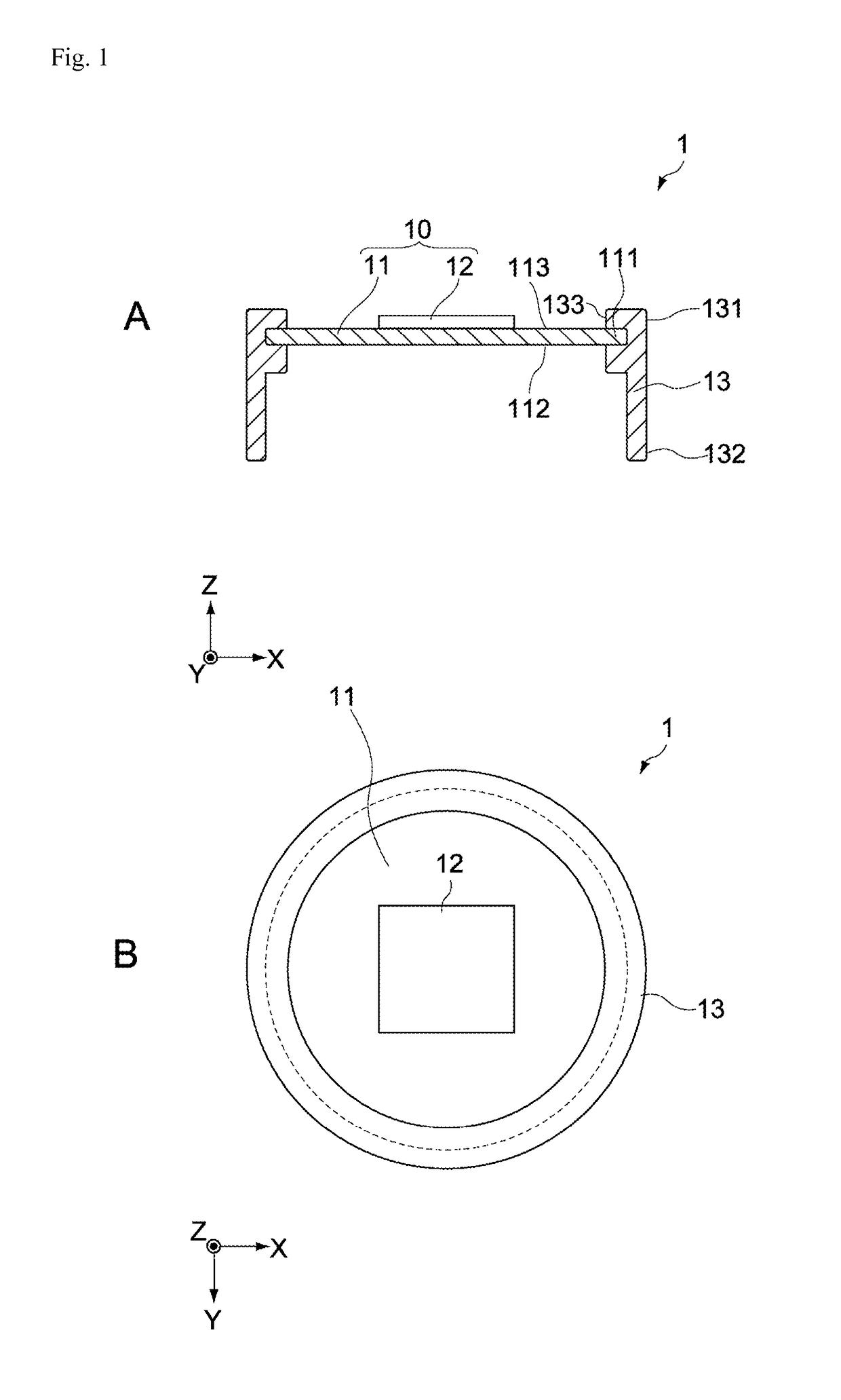
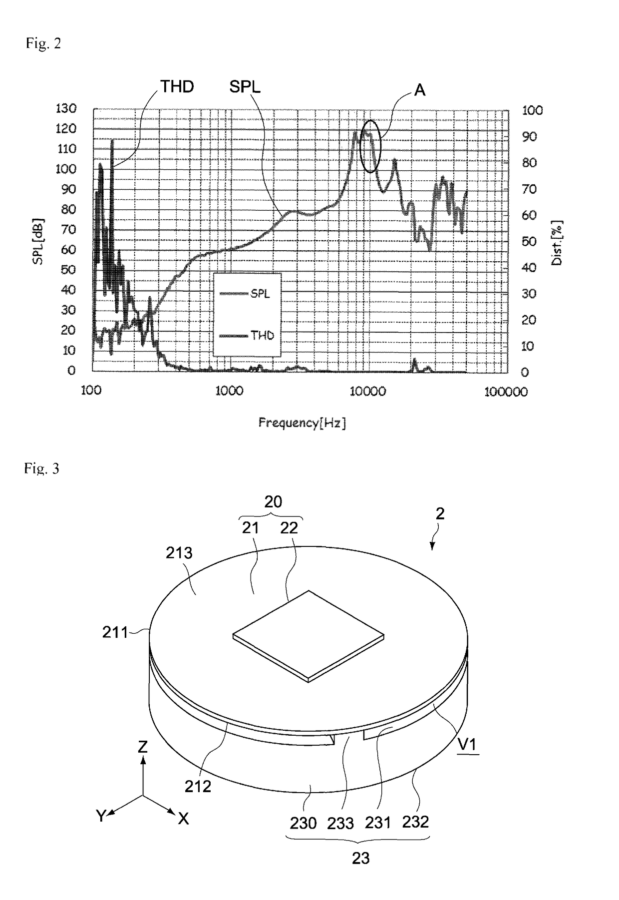
[0066]FIG. 3 is a general perspective view of a speaker unit of the electroacoustic transducer pertaining to the first embodiment of the present invention, while FIG. 4 and FIG. 5 are an exploded perspective view and schematic lateral section view of the same, respectively.
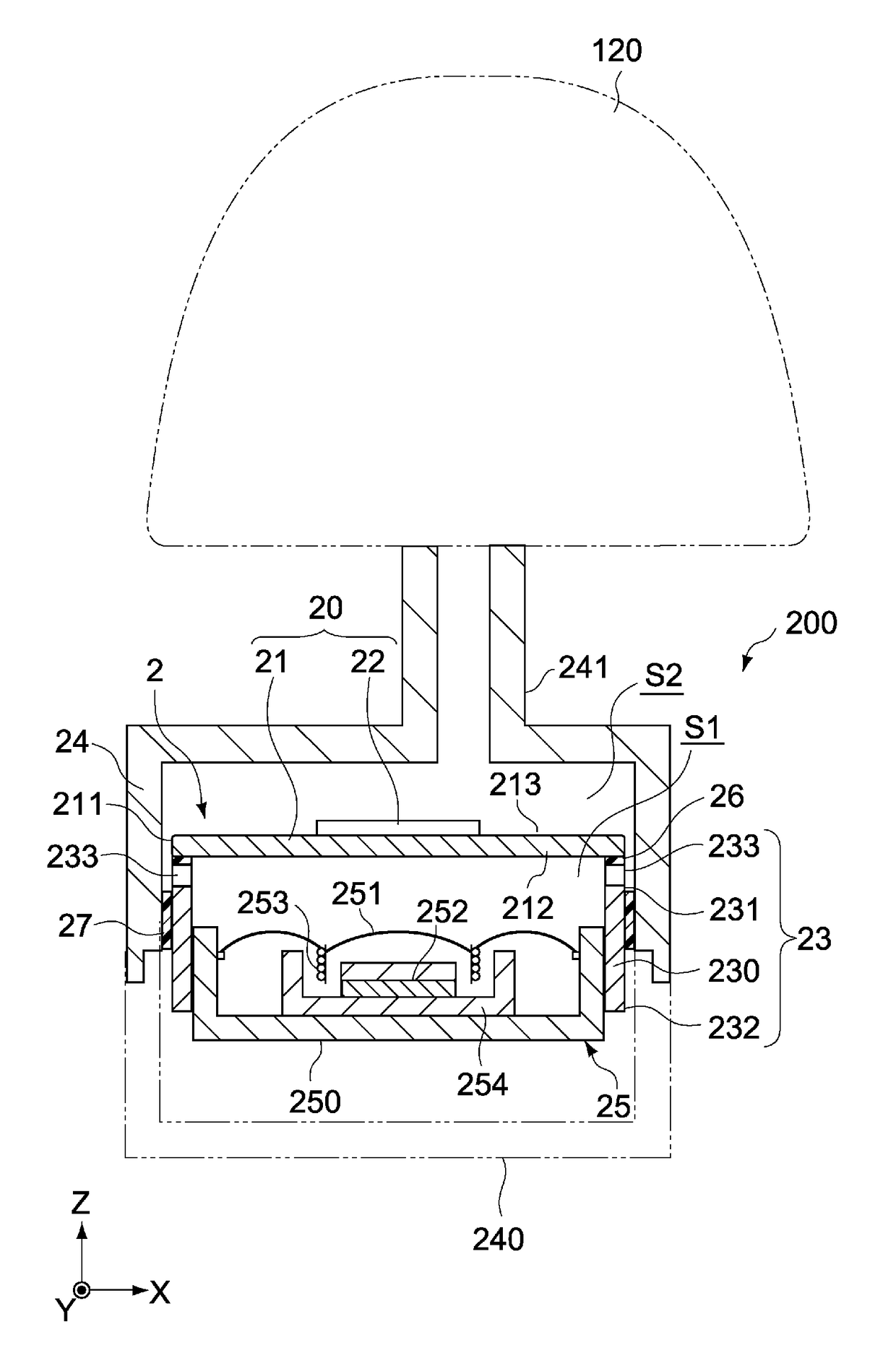
[0067]A speaker unit 2 pertaining to this embodiment has a piezoelectric speaker 20 and support member 23. The speaker unit 2 is housed inside a housing not illustrated here, to constitute an electroacoustic transducer for an earphone, headphone, etc.
[0068]The piezoelectric speaker 20 has a vibration plate 21 having a first surface 212 and a second surface 213 on the opposite side of the first surface, as well as a piezoelectric element 22. The piezoelectric element 22 is integrally joined to at least one of the first surface 212 and second surface 213 of the vibration plate 21. In the example shown, the piezoelectric element 22 is joined to the second surface 213. The vibration plate 21 and piezoelectric element ...
second embodiment
[0091]FIG. 8 is a schematic lateral section view showing the constitution of an electroacoustic transducer 300 pertaining to the second embodiment of the present invention. Constitutions different from those of the first embodiment are primarily explained below, and the same constitutions as in the first embodiment are not explained or explained briefly using the same symbols.
[0092]The electroacoustic transducer 300 in this embodiment includes a speaker unit 3 having a dynamic speaker 25, and a housing 24, as shown in FIG. 8. It should be noted that the interior structure of the dynamic speaker 25 is not illustrated.
[0093]In this embodiment, a support member 33 has a supporting part (ring-shaped convex 333) facing a first surface 212 of a vibration plate 21, and supports a periphery 211 of the vibration plate 21 with the supporting part. The support member 33 may be constituted by a part of the housing or by a member different from the housing.
[0094]The support member 33 has an annu...
third embodiment
[0104]A and B in FIG. 11 are a schematic lateral section view and cross section view, respectively, showing the constitution of an electroacoustic transducer 400 being an electroacoustic transducer pertaining to the third embodiment of the present invention. Constitutions different from those of the first embodiment are primarily explained below, and the same constitutions as in the first embodiment are not explained or explained briefly using the same symbols.
[0105]The electroacoustic transducer 400 in this embodiment has a speaker unit 4 with a dynamic speaker 25, and a housing 24, as shown in A in FIG. 11. It should be noted that the interior structure of the dynamic speaker 25 is not illustrated.
[0106]In this embodiment, a support member 43 has supporting parts (multiple projections 433) facing a first surface 212 of a vibration plate 21, and supports a periphery 211 of the vibration plate 21 with the supporting parts.
[0107]The support member 43 may be constituted by a part of t...
PUM
 Abstract
Description
Claims
Application Information
 - R&D
- Intellectual Property
- Life Sciences
- Materials
- Tech Scout
- Unparalleled Data Quality
- Higher Quality Content
- 60% Fewer Hallucinations
Browse by: Latest US Patents, China's latest patents, Technical Efficacy Thesaurus, Application Domain, Technology Topic, Popular Technical Reports.
© 2025 PatSnap. All rights reserved.Legal|Privacy policy|Modern Slavery Act Transparency Statement|Sitemap|About US| Contact US: help@patsnap.com


