Method for Producing a Glass Pane

a glass pane and glass technology, applied in glass severing devices, glass making apparatus, packaging, etc., can solve the problems of poor edge strength, thermally cut edge strength, and decrease the edge strength, so as to reduce the danger of damage, wide application and use confiden

Inactive Publication Date: 2009-10-01
FRAUNHOFER GESELLSCHAFT ZUR FOERDERUNG DER ANGEWANDTEN FORSCHUNG EV
View PDF10 Cites 30 Cited by
  • Summary
  • Abstract
  • Description
  • Claims
  • Application Information

AI Technical Summary

Benefits of technology

[0011]The invention has the objective of reducing the danger of damage to thermally cut glass at the glass edges, so that thermally cut glass may be supplied for wider application and confident use.
[0016]The sheath preferably comprises a permanently[-] elastic plastic material, which is preferably applied flush along the edge section. The sheath covers both the front face of the edge section and also boundary areas of the glass pane faces directly adjoining the front face. It is thus ensured that the damage-sensitive edge lines are completely enclosed by the sheath. Plastics which adhere to glass are suitable with especially preferable sheath material, such as elastomers, preferably organic elastomers, for example, polyurethane, acrylic lacquer, acrylates in connection with polyurethane, polyisocyanate, silicone, epoxide resin, PVC, etc. To increase the adhesive strength on glass of plastic-based sheath material, an appropriate primer additive may additionally be used.
[0020]Alternatively to the use of sheath materials adhering directly to the glass and front face top sides, sheaths are also usable which do enclose the front face of the edge area, but do not contact it directly, but rather stretch over and / or around it in an arc. In this case, the sheath adheres and / or presses against the boundary areas of the two glass pane faces adjoining the front face in the edge area. By the contactless configuration of the sheath in relation to the front face, it may be ensured that the properties of the front face determining the strength of the edge area and those of the edge curves remain completely uninfluenced, but nonetheless care is taken here to effectively protect particularly these areas from external mechanical effects. Because of the intrinsic elasticity of the particular selected sheath material and by providing a cavity enclosed with the edge area, with a design of the sheath of this type, a type of crumple zone is provided, by which the edge area is protected from external mechanical influences.
[0022]It is obvious that the size and geometry selection of the sheath protecting the particular edge area is a function of the particular thickness and size of the glass pane itself. Thus, in a simplest construction having small dimensions, the sheath may be implemented in the form of a thin lacquer layer, which locally encloses the edge area. However, if thicker and larger-area glass panes are used, sheaths having a thickness of a few millimeters up to a few centimeters or decimeters may be selected. If the mechanical protection of sheaths usually manufactured from plastic materials is to be improved further, the combination with separately selected reinforcement materials is suitable, which may themselves comprise thermoplastics or metals, for example, such as aluminum or steel, and which may be embedded in the sheath or applied to the particular surface of the sheath. A preferred embodiment, for example, provides an external additional metal sheath, which encloses the sheath typically manufactured from elastic plastic material.
[0023]In addition to solely protecting the edge area from external mechanical influences, the sheath is capable of unifying additional functional properties, depending on the design and dimensioning, such as a sealing function or a fitting function for installation in frame systems enclosing the glass pane. As already noted at the beginning, the measure according to the solution is to simplify the handling and integration of thermally cut glass panes in buildings or facility areas, for example, without an excess of care having to be taken in regard to the breaking danger of an exposed thermally cut glass pane edge.

Problems solved by technology

In addition to the severing of flat glasses via mechanical scoring using a scoring wheel and subsequent bending fracture and the resulting known poor edge qualities thus arising, caused by local boundary chipping and low strength of the glass, methods exist in selected marked areas application, in which the glass pane is either severed by a crack cutting through the glass pane which is driven by thermal tensions or a crack running in the glass surface which is also driven by thermal tensions and the subsequent bending fracture.
The strength of the thermally cut edges is so great that processing steps such as edging, beveling, grinding, or polishing contribute more to decreasing the edge strength and worsening the edge quality, particularly because flaws may be introduced into the edge in this way.
In addition, the amount of strength increase obtained using the thermally induced edge production does not even represent the limit of the maximum achievable edge strength, but rather is limited by the flaws introduced into the glass surfaces during the production and further processing process of float glass.
However, it is known that glass is capable of having a significantly higher strength, but this is not achievable as a result of the inadequate edge quality after mechanical scoring and breaking and with subsequent processing of the glass edge.
Until now, many applications of glass as a supporting material have therefore not been possible using the glass panes available until now.
Because of a sharp transition of the thermally cut edge to the glass surface which forms, however, the edge is disadvantageously especially impact-sensitive, however, so that even slight mechanical strains, for example, caused by being set down, hitting against another glass edge, etc., as commonly occur during correct handling, during transport, further processing, and the installation and use of glass panes, for example, may automatically result in edge damage, from microscopically small to chips and damage visible with the naked eye.
Smaller flaws in the edges decrease the edge strength and in the event of larger damage, the edge strength suffers in an amount up to the level of a mechanically scored and broken glass pane.
High edge strength and the advantages connected thereto, such as lesser material requirement, equal strength or greater strength reserves which occurs with identically dimensioned panes, in comparison to the properties resulted from mechanical scoring and breaking, may be lost irretrievably with edge damage.
The existing danger of damage explained above prevents a broad application of high strength thermally cut glass.

Method used


Image

  • Method for Producing a Glass Pane
  • Method for Producing a Glass Pane
  • Method for Producing a Glass Pane

Examples


Embodiment Construction

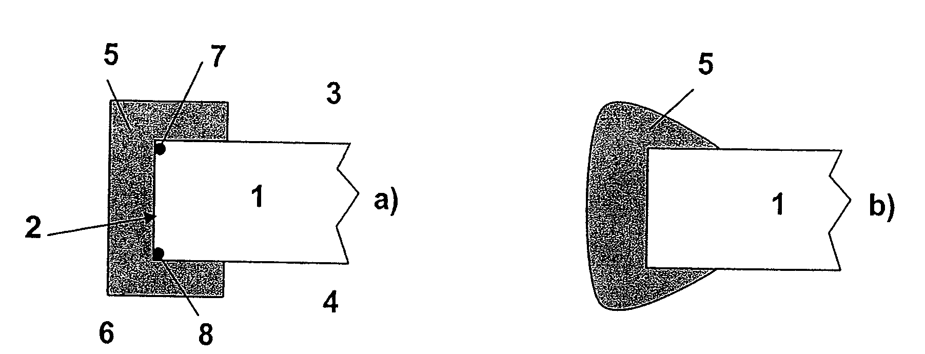
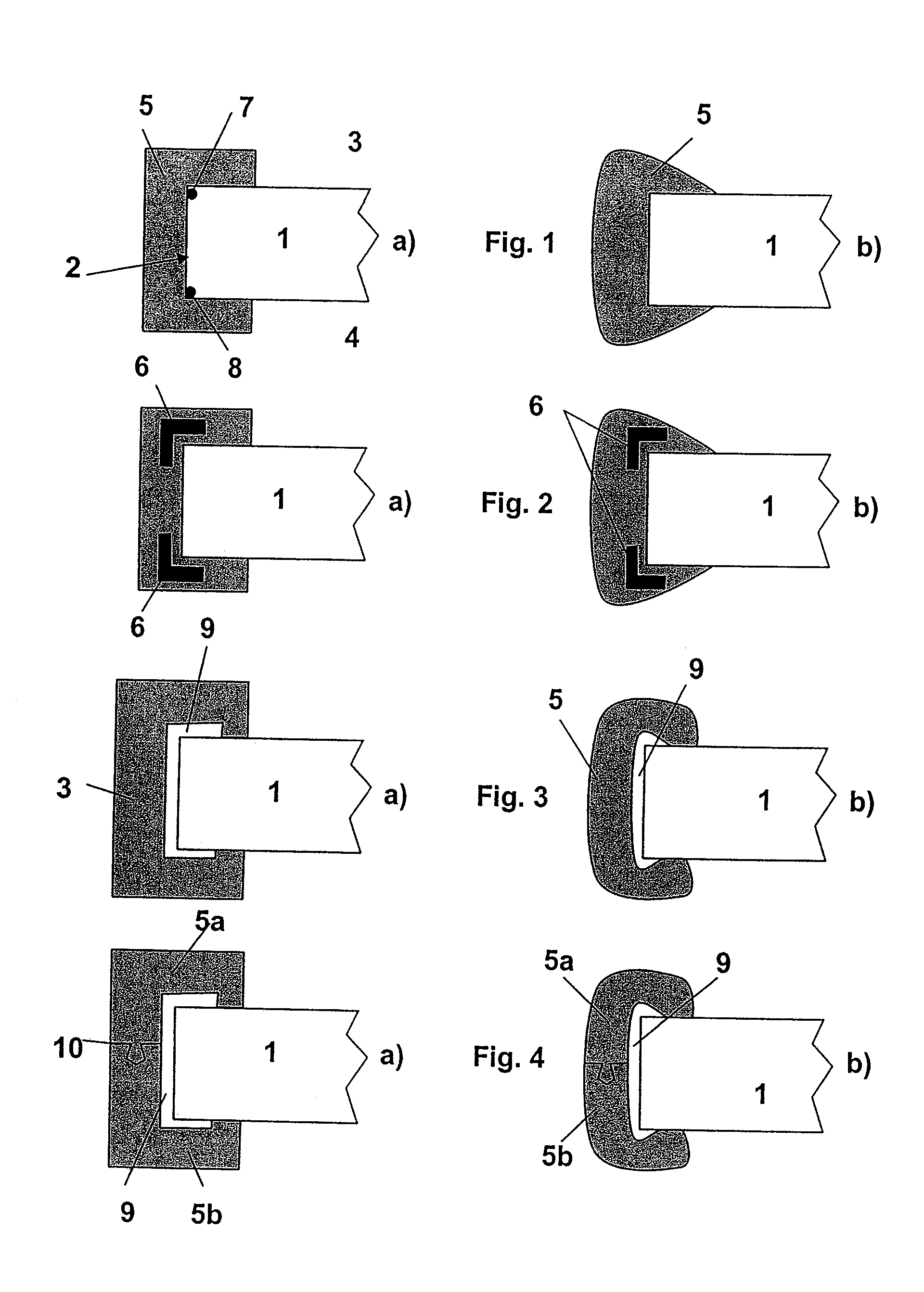
[0030]FIGS. 1a and b each show a typical cross-section through a glass pane 1 in the boundary area, in which it is to be assumed that the edge section has been produced with the aid of a thermal energy introduction. The edge section itself has a front face 2, which typically intersects the opposing glass pane faces 3 and 4 perpendicularly. This assumption applies for all exemplary embodiments shown and may be assumed to be largely realistic, although production-related deviations from an exactly orthogonal orientation of the front face 2 in relation to the adjoining glass pane faces 3 and 4 may occur.

[0031]A sheath 5 enclosing the front face and the boundary areas of the glass pane 3, 4 is shown in FIG. 1a, which adheres directly on the particular glass surface of the edge area. It is to be assumed that the sheath 5 comprises a self-curing plastic material which may be cast, poured, sprayed on, or molded in another suitable way. The embodiment according to FIG. 1a is a perfectly-geo...


PUM

PropertyMeasurementUnit
thermal energyaaaaaaaaaa
mechanical tensionaaaaaaaaaa
forceaaaaaaaaaa

Abstract

A method is described for producing a glass pane having at least one edge section delimiting the glass pane, for whose production the glass pane has been severed along the edge section with the aid of a severing procedure comprising a thermal energy introduction.The invention of the glass pane is enclosed at least sectionally and preferably along the entire edge section by a sheath immediately after production of the at least one edge section using a severing procedure comprising a thermal energy introduction.

Description

BACKGROUND OF THE INVENTION[0001]1. Field of the Invention[0002]The invention relates to a method for producing a glass pane having at least one edge section, in which during production of the glass pane the edge section has been severed by a severing procedure comprising introduction of a thermal energy and to a glass pane which has been produced using the method.[0003]2. Description of the Prior Art[0004]In addition to the severing of flat glasses via mechanical scoring using a scoring wheel and subsequent bending fracture and the resulting known poor edge qualities thus arising, caused by local boundary chipping and low strength of the glass, methods exist in selected marked areas application, in which the glass pane is either severed by a crack cutting through the glass pane which is driven by thermal tensions or a crack running in the glass surface which is also driven by thermal tensions and the subsequent bending fracture. The combination of both methods is conceivable. A ver...

Claims


Application Information

Patent Timeline
Patent Type & Authority Applications(United States)
IPC IPC(8): B23P11/00
CPCB65D81/053B65G49/069Y10T29/49826C03B33/091C03B33/09B65D81/055
Inventor KUBLER, RAINERKLEER, GUNTERKOLLOFF, RAINERKRAPPITZ, MARTINFABER, THORSTEN
Owner FRAUNHOFER GESELLSCHAFT ZUR FOERDERUNG DER ANGEWANDTEN FORSCHUNG EV
Why Eureka
Try Eureka