Vertical rod fixing piece and scaffold

A technology of fixing parts and poles is applied in the accessories of scaffolding, scaffolding supported by house structure, buildings, etc. It can solve the problems of poor structural mechanical properties, easy damage and deformation, and high labor costs, and achieve structural strength and safety improvement. resistance, avoid the effect of unloading failure

Pending Publication Date: 2018-01-09
CCCC FOURTH HIGHWAY ENG
View PDF14 Cites 6 Cited by
  • Summary
  • Abstract
  • Description
  • Claims
  • Application Information

AI Technical Summary

Problems solved by technology

[0008] The object of the present invention is to provide a kind of vertical rod fixing part and scaffolding, to solve the problems of poor structural mechanical properties, high risk, high labor cost, etc. Easily damaged and deformed

Method used


Image

  • Vertical rod fixing piece and scaffold
  • Vertical rod fixing piece and scaffold
  • Vertical rod fixing piece and scaffold

Examples


Embodiment 1

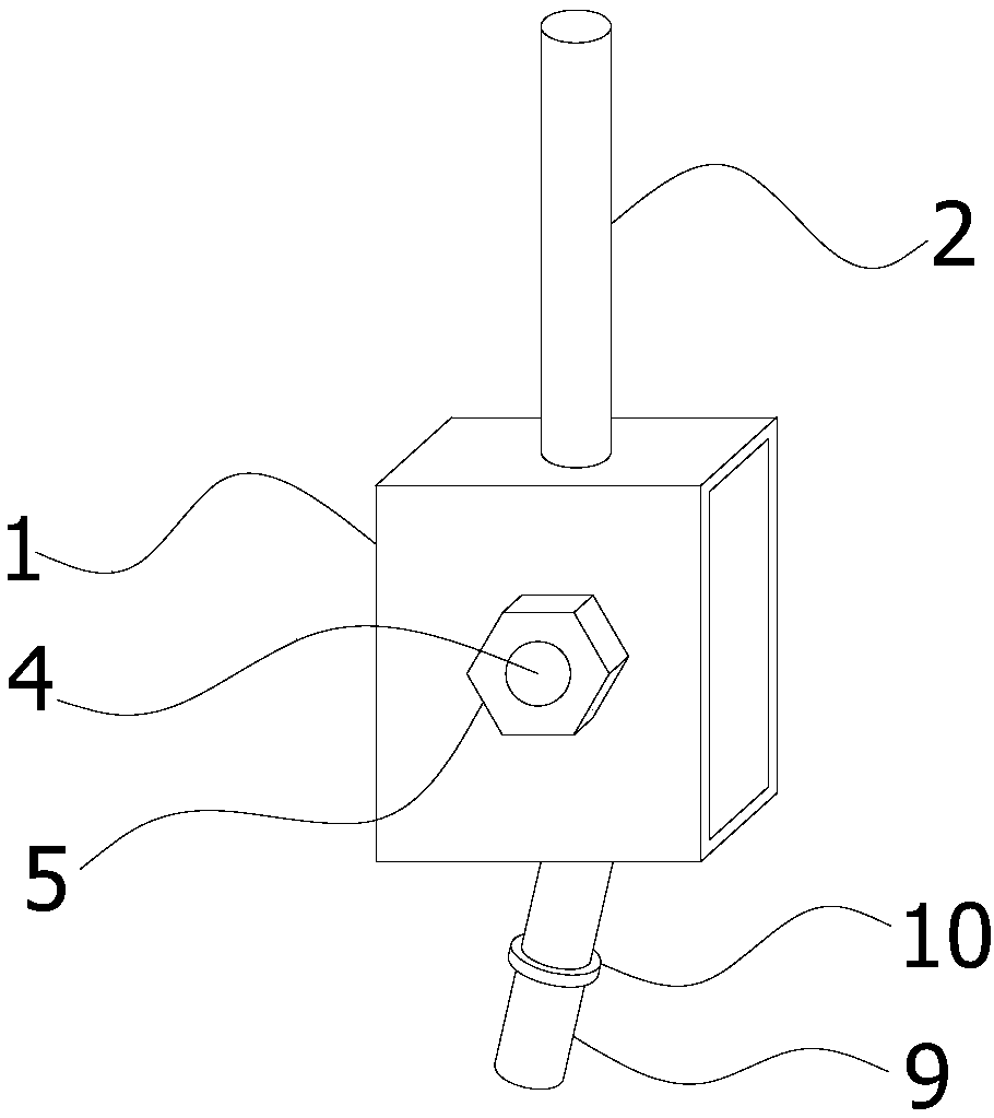
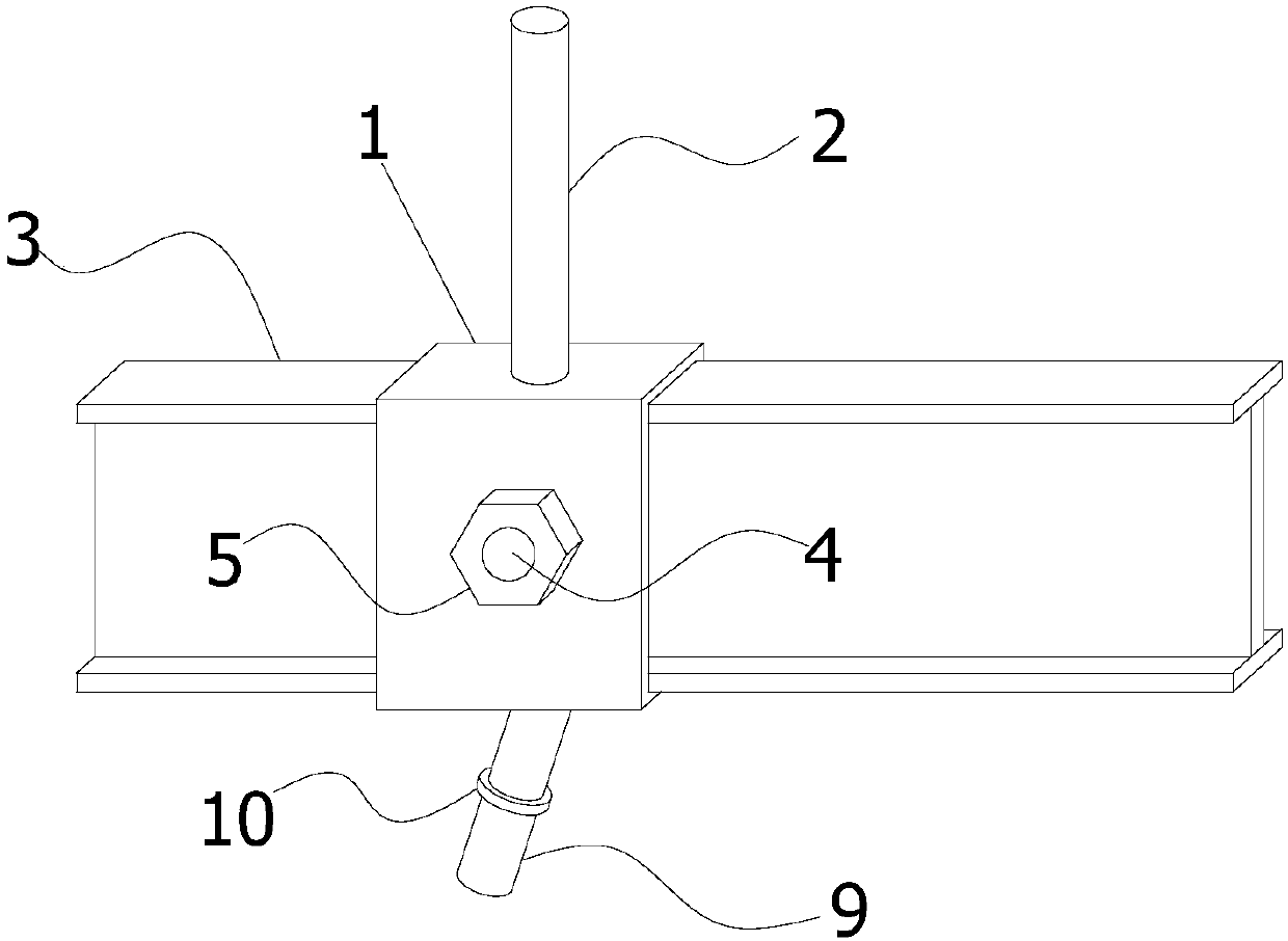
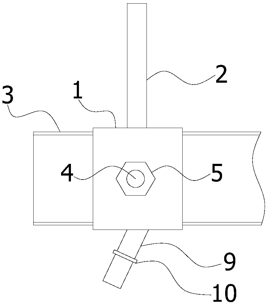
[0044] This embodiment provides a pole fixture, wherein: figure 1 An axonometric view of the pole fixture provided by the embodiment of the present invention; figure 2 An axonometric view of the vertical pole fixing piece provided for the embodiment of the present invention after the I-beam cantilever 3 is sleeved; image 3 The front view of the pole fixing piece provided for the embodiment of the present invention after the I-beam cantilever 3 is sleeved; Figure 4 It is a left side view of the pole fixing piece provided in Embodiment 1 of the present invention after being fitted with the I-beam cantilever 3 . Such as Figure 1~4 As shown, the pole fixing piece includes a fixing sleeve 1, a fixing rod 2 and a fastening assembly. Specifically, the inner cavity of the fixing sleeve 1 can be fit and socketed with the outer contour of the I-shaped steel cantilever 3, and the fastening assembly is arranged on the fixing sleeve 1 for firmly installing the fixing sleeve 1 on the...

Embodiment 2

[0050] This embodiment provides a pole fixture, wherein: Figure 5 It is a left side view of the pole fixing piece provided in Embodiment 2 of the present invention after being fitted with the I-beam cantilever 3 . Such as Figure 1~3 , 5, the pole fixing piece includes a fixing sleeve 1, a fixing rod 2 and a fastening assembly. Specifically, the inner cavity of the fixing sleeve 1 can be fit and socketed with the outer contour of the I-shaped steel cantilever 3, and the fastening assembly is arranged on the fixing sleeve 1 for firmly installing the fixing sleeve 1 on the I-shaped beam. The exterior of the steel cantilever 3. Wherein, the fixed rod 2 is welded on the fixed sleeve 1 for inserting and fixing the vertical rod of the scaffold.

[0051] Further, the fastening assembly includes bolts 4, nuts 5 and through holes 6, wherein the through holes 6 are arranged on the two side walls of the fixing sleeve 1, and the bolts 4 pass through the through holes 6 of one side wal...

Embodiment 3

[0055] This embodiment provides a pole fixture, wherein: Figure 6 It is a left view of the pole fixing piece provided in Embodiment 3 of the present invention after being fitted with the I-beam cantilever 3 . Such as Figure 1~3 , 6, the pole fixing piece includes a fixing sleeve 1, a fixing rod 2 and a fastening assembly. Specifically, the inner cavity of the fixing sleeve 1 can be fit and socketed with the outer contour of the I-shaped steel cantilever 3, and the fastening assembly is arranged on the fixing sleeve 1 to securely install the fixing sleeve 1 on the I-shaped beam. The exterior of the steel cantilever 3. Wherein, the fixed rod 2 is welded on the fixed sleeve 1 for inserting and fixing the vertical rod of the scaffold.

[0056] Further, the fastening assembly includes bolts 4 and screw holes 8 . Wherein, the screw hole 8 is provided on the side wall of the fixing sleeve 1 , and the bolt 4 passes through the screw hole 8 and contacts the I-beam beam 3 , so tha...


PUM


Abstract

The invention provides a vertical rod fixing piece comprising a fixing sleeve, a fixing rod and a fastening assembly. An inner cavity of the fixing sleeve can be connected with the outer contour of anI-shaped steel cantilever beam in attached and sleeving modes. The fastening assembly is arranged on the fixing sleeve and used for firmly mounting the fixing sleeve on the exterior of the I-shaped steel cantilever beam. The fixing rod is welded to the fixing sleeve and used for inserting and fixing a vertical rod of a scaffold. According to the vertical rod fixing piece, by using the fixing sleeve with the welded fixing rod, the situation that the fixing rod is directly welded to the I-shaped steel cantilever beam is avoided, and the damage hidden danger of the I-shaped steel cantilever beamand the fixing rod in construction operation due to stress concentration is reduced; during mounting and demounting, an I-shaped steel cantilever beam without a welded fixing rod can penetrate through a shear wall independently, the aerial operation procedures are simplified, and the construction risks are reduced; and meanwhile, the collision deformation risk of scaffold parts in the process that the scaffold parts are stored and transported to other sites is also avoided. On the basis of the vertical rod fixing piece, the invention further provides the scaffold.

Description

technical field [0001] The invention relates to the technical field of construction equipment, in particular to a pole fixing piece and a scaffold. Background technique [0002] Cantilevered scaffolding refers to the scaffolding structure unloaded on the rigid cantilever beam (frame) attached to the building structure. It is used for the main body or decoration project in construction and its safety protection needs. The erection height shall not be greater than 20m. [0003] In the prior art, the structure of the vertical pole positioning part at the end of the cantilever beam of the cantilevered scaffold is: a steel bar with a diameter of 20 mm and a height of 200 mm is welded at a distance of 100 mm from the center line of the flange above the end of the I-beam cantilever beam. . The scaffolding pole is inserted on the steel bar to play the role of fixing the pole. Weld a steel bar with a diameter of 20mm and a height of 100mm at a distance of 100mm from the center lin...

Claims


Application Information

Patent Timeline
Patent Type & Authority Applications(China)
IPC IPC(8): E04G3/18E04G5/04
Inventor 郭帅文刘少轩郑毅
Owner CCCC FOURTH HIGHWAY ENG
Why Eureka
Try Eureka