Remote control weapon lock

a remote control and weapon technology, applied in the field of weapons locks, can solve the problems of compromising the lock itself and limiting the use of the gun,

Active Publication Date: 2016-09-22
MILDE KARL F JR
View PDF3 Cites 8 Cited by
  • Summary
  • Abstract
  • Description
  • Claims
  • Application Information

AI Technical Summary

Benefits of technology

[0005]It is a principal object of the present invention to provide a gun safety system for a trigger-operated gun which is difficult to compromise and allows only the gun owner, or some other person who is licensed or otherwise authorized to use the gun.

Problems solved by technology

These gun locks use a mechanical key that can be easily duplicated, and the locks themselves can be compromised by means of a master key or a lock pick.
With such gun locks it is not possible to restrict the use of the gun to the gun owner or to some other person who is licensed or otherwise authorized to use the gun.

Method used


Image

  • Remote control weapon lock
  • Remote control weapon lock
  • Remote control weapon lock

Examples


Embodiment Construction

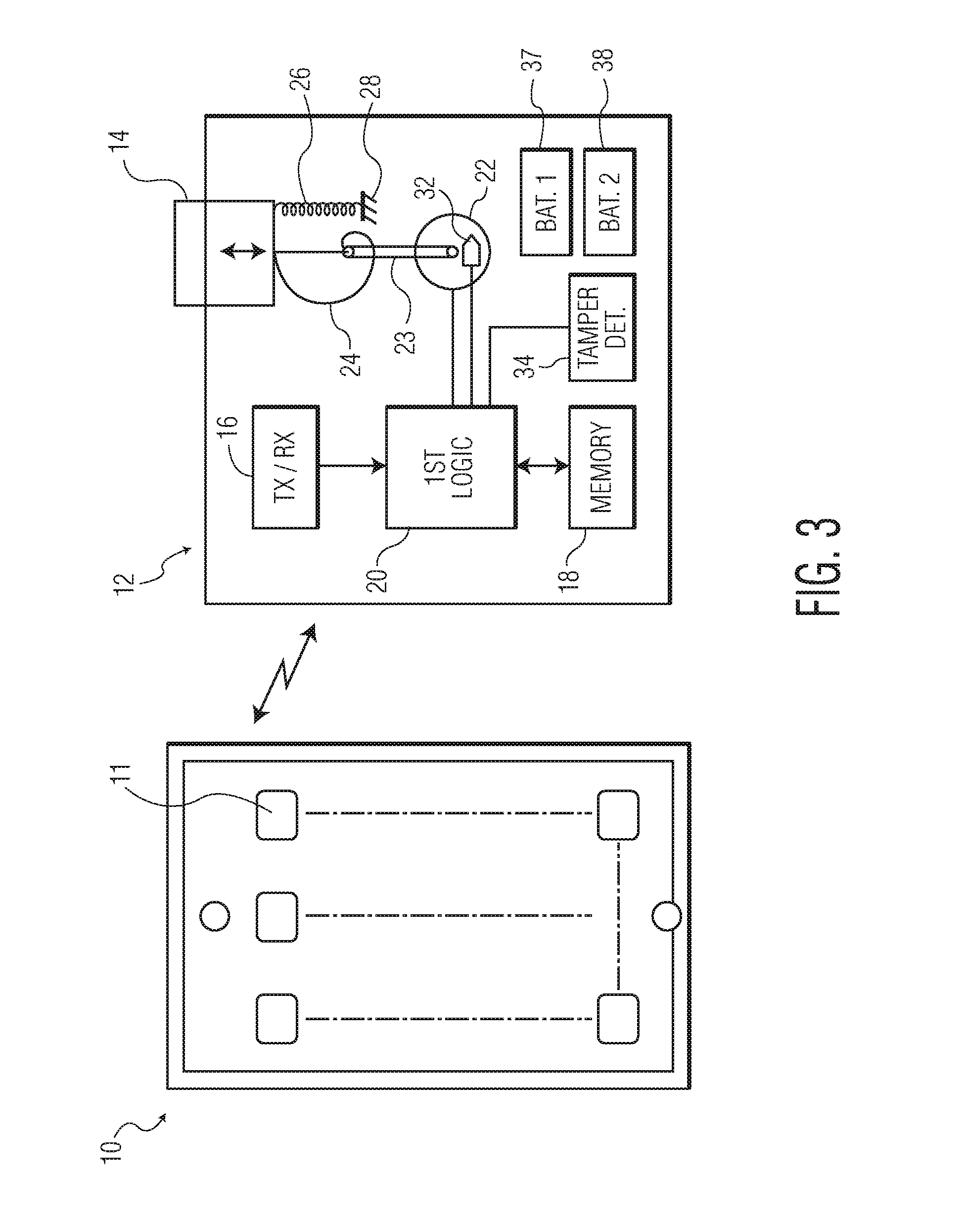
[0050]The preferred embodiments of the present invention will now be described with reference to FIGS. 1-7 of the drawings. Identical elements in the various figures are identified with the same reference numerals.

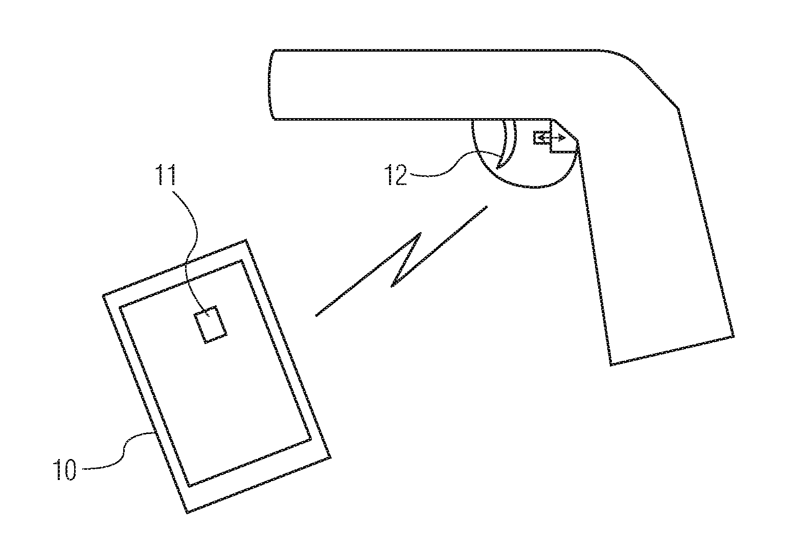
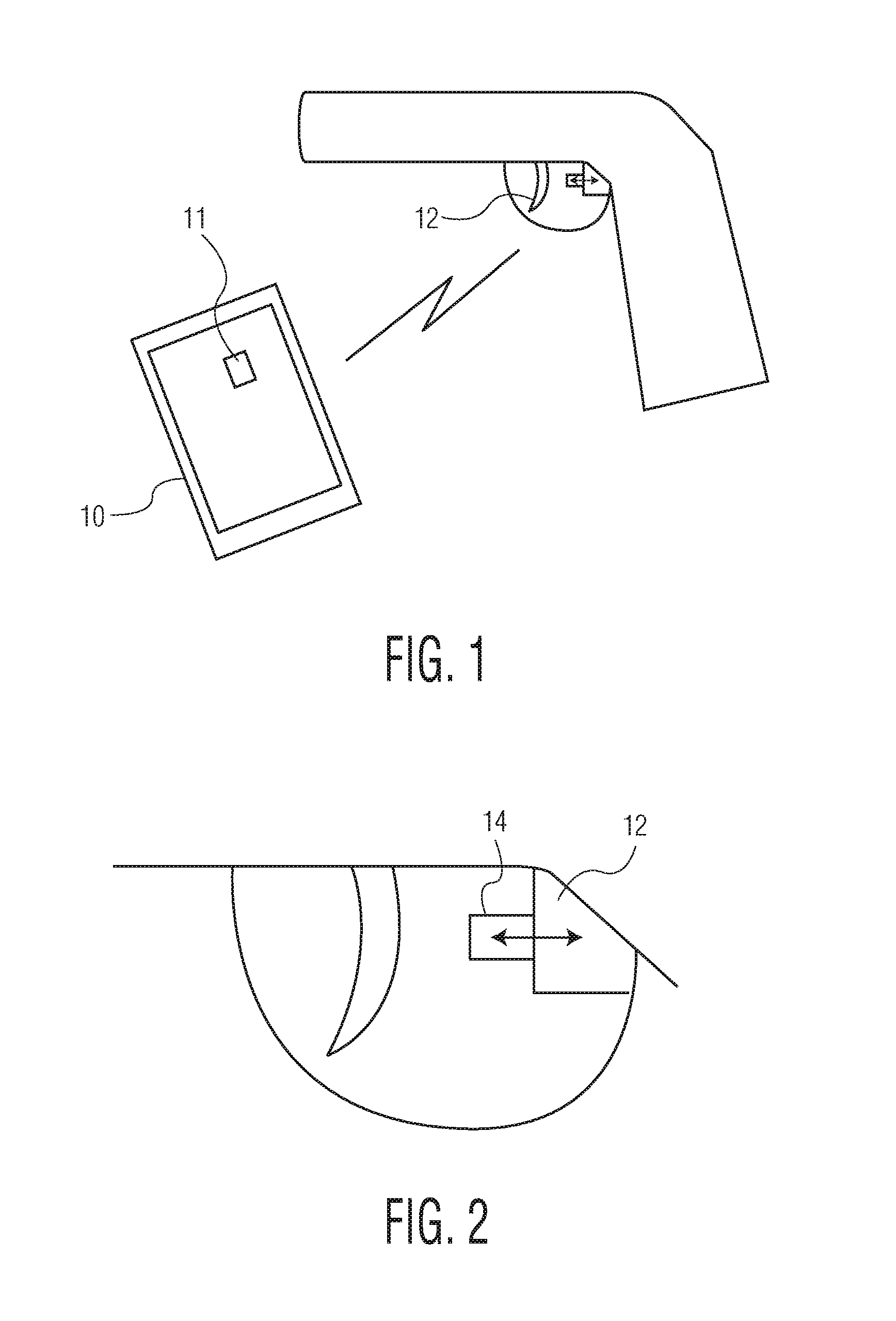
[0051]Briefly in overview, a battery-operated trigger-locking device is permanently attached to / installed in a gun in a recess behind the trigger in the lower receiver mechanism. In its default condition, a movable member is in a blocking position, preventing movement of the trigger. When unlocked, the movable member is drawn rearward, or otherwise removed from its blocking position, to allow movement of the trigger.

[0052]The trigger-locking device has a Bluetooth (or other type) receiver and a storage device for storing personal information identifying an authorized user of the gun. When this particular information is received from a smartphone or similar device, the trigger-locking device removes the movable member from the blocking position, releasing the trigger.

[0053]...


PUM


Abstract

A battery-powered trigger-locking device, which is configured to be disposed on a gun with a trigger for firing, includes a data receiver, a data memory and a logic device for determining whether data received by the receiver is the same, or substantially the same, as data stored in the memory. If a data match is indicated, the logic device causes an electromagnetic device to move a trigger-locking member to an unlocked position, permitting the gun to be fired. A separate electronic gun key is provided to transmit gun unlock data to the data receiver of the trigger-locking device. This gun unlock data may be a password, a long pseudo-random number or biologic data identifying the gun owner or some other person who is licensed or otherwise authorized to fire the gun.

Description

CROSS-REFERENCE TO RELATED APPLICATIONS[0001]This application claims priority from the U.S. Provisional Application No. 61 / 761,270 filed Feb. 6, 2013, and entitled “SECURE SMARTPHONE-OPERATED GUN TRIGGER LOCK;” the U.S. patent application Ser. No. 13 / 763,951 filed Feb. 11, 2013, entitled “SECURE SMARTPHONE-OPERATED GUN TRIGGER LOCK” (now U.S. Pat. No. 8,893,420); U.S. patent application Ser. No. 14 / 511,222 filed Oct. 10, 2014, entitled “SECURE SMARTPHONE-OPERATED LOCKING DEVICE” (now U.S. Pat. No. 9,222,740); and U.S. patent application Ser. No. 14 / 542,889 filed Nov. 17, 2014, entitled “REMOTE CONTROL WEAPON LOCK” (now allowed). This application is a continuation-in-part of said application Ser. No. 14 / 542,889.BACKGROUND OF THE INVENTION[0002]The present invention relates to a weapon lock, such as, for example, a gun lock for a trigger-operated gun which is designed to be installed on the gun in a position behind the trigger to prevent the trigger from firing the gun.[0003]Mechanica...

Claims


Application Information

Patent Timeline
Patent Type & Authority Applications(United States)
IPC IPC(8): F41A17/06
CPCF41A17/066F41A17/063F41A17/22F41A17/46
Inventor MILDE, JR., KARL F.MATOS, JEFFREY A.
Owner MILDE KARL F JR
Why Eureka
Try Eureka