Secure smartphone-operated gun trigger lock

a smartphone-operated, gun-operated technology, applied in the direction of weapons, weapon components, safety arrangements, etc., can solve the problems of tampering or removal of the gun lock, the lock itself can be compromised, and the restriction of the use of the gun lock is possibl

Active Publication Date: 2016-04-12
MILDE JR KARL F
View PDF9 Cites 7 Cited by
  • Summary
  • Abstract
  • Description
  • Claims
  • Application Information

AI Technical Summary

Benefits of technology

[0006]It is a principal object of the present invention to provide a gun lock for a trigger-operated gun which is difficult to compromise and allows only the gun owner, or some other person who is licensed or otherwise authorized to use the gun.
[0011](1) a gun lock mechanism, responsive to a gun command signal, for preventing firing of the gun when in a locked state and enabling firing of the gun when in an unlocked state;
[0020]Preferably, the first logic device is operative to set said gun lock mechanism in the locked state and prevent firing of the gun when said tamper alert is detected.
[0031]maintain the locking member in the locked position at all other times, thereby to prevent unauthorized operation of the gun.
[0059]Advantageously, the data memory comprises at least one write-once-only element to prevent degradation of the data stored in the memory and to prevent the data stored in the memory from being changed. The write-once-only element may be a PROM, an EPROM or an EEPROM, for example.

Problems solved by technology

These gun locks use a mechanical key that can be easily duplicated, and the locks themselves can be compromised by means of a master key or a lock pick.
With such gun locks it is not possible to restrict the use of the gun to the gun owner or to some other person who is licensed or otherwise authorized to use the gun.
However, it is not possible to prevent the tampering or removal of this gun lock by an unauthorized person who wishes to use the gun.

Method used


Image

  • Secure smartphone-operated gun trigger lock
  • Secure smartphone-operated gun trigger lock
  • Secure smartphone-operated gun trigger lock

Examples


Embodiment Construction

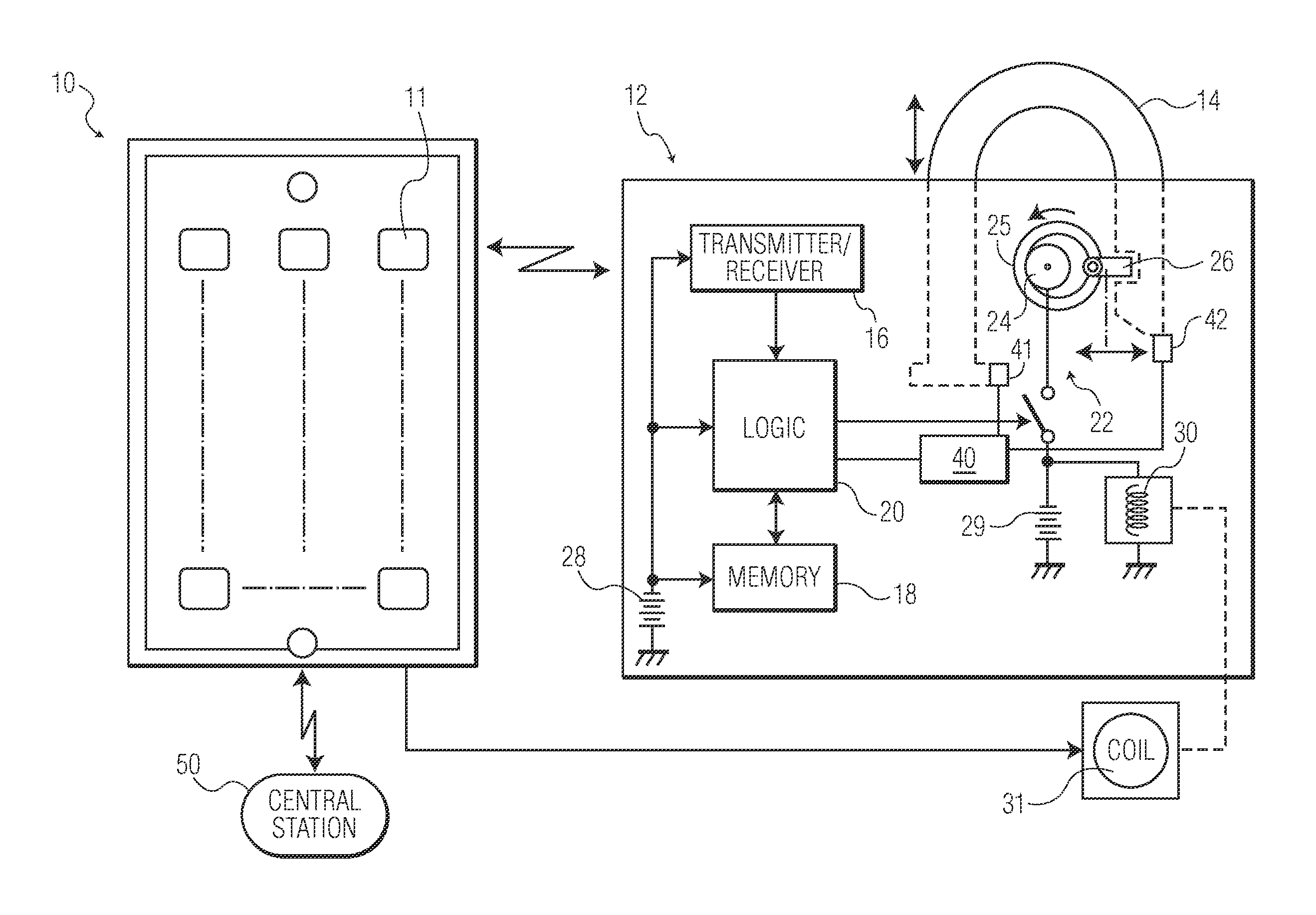
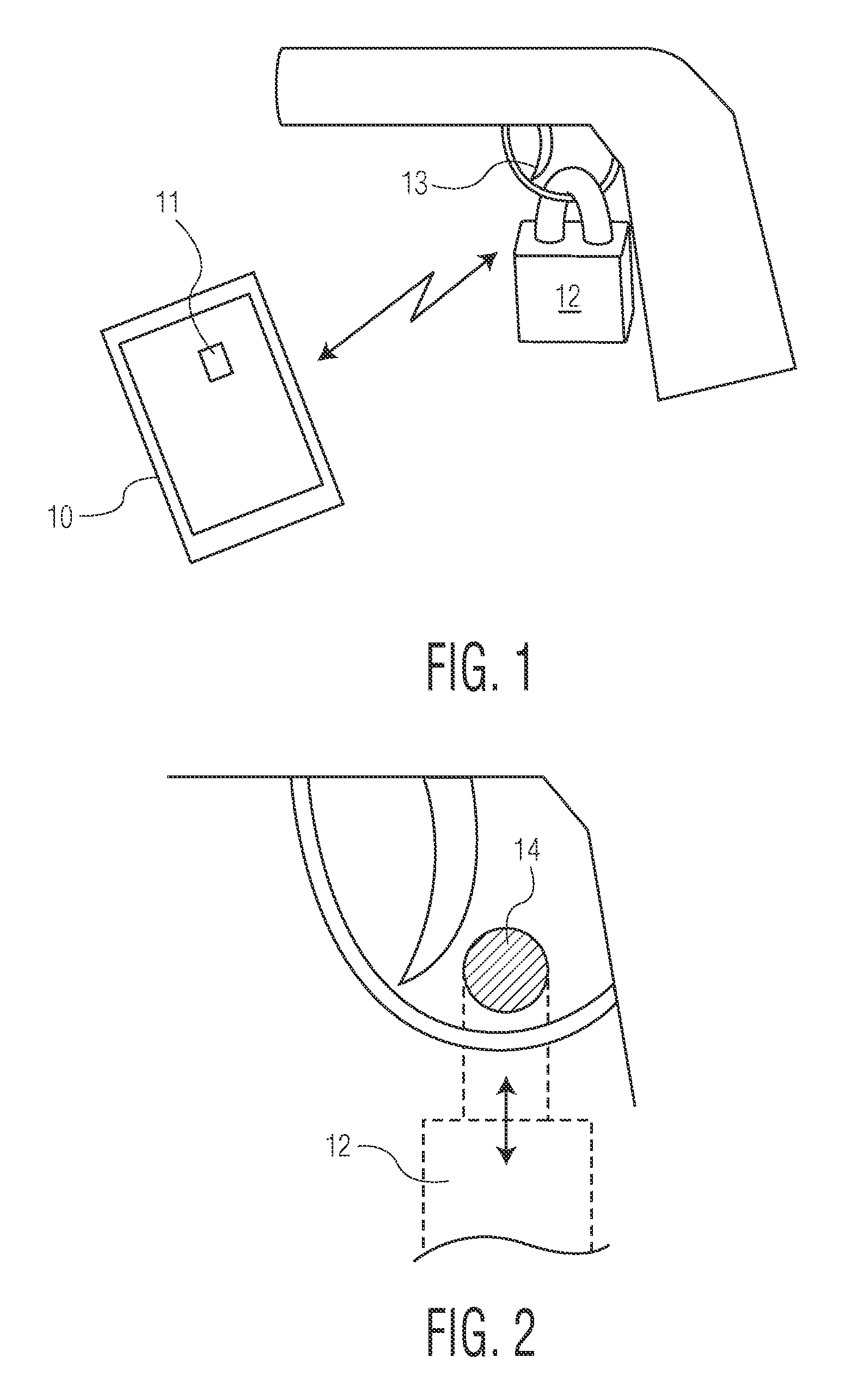
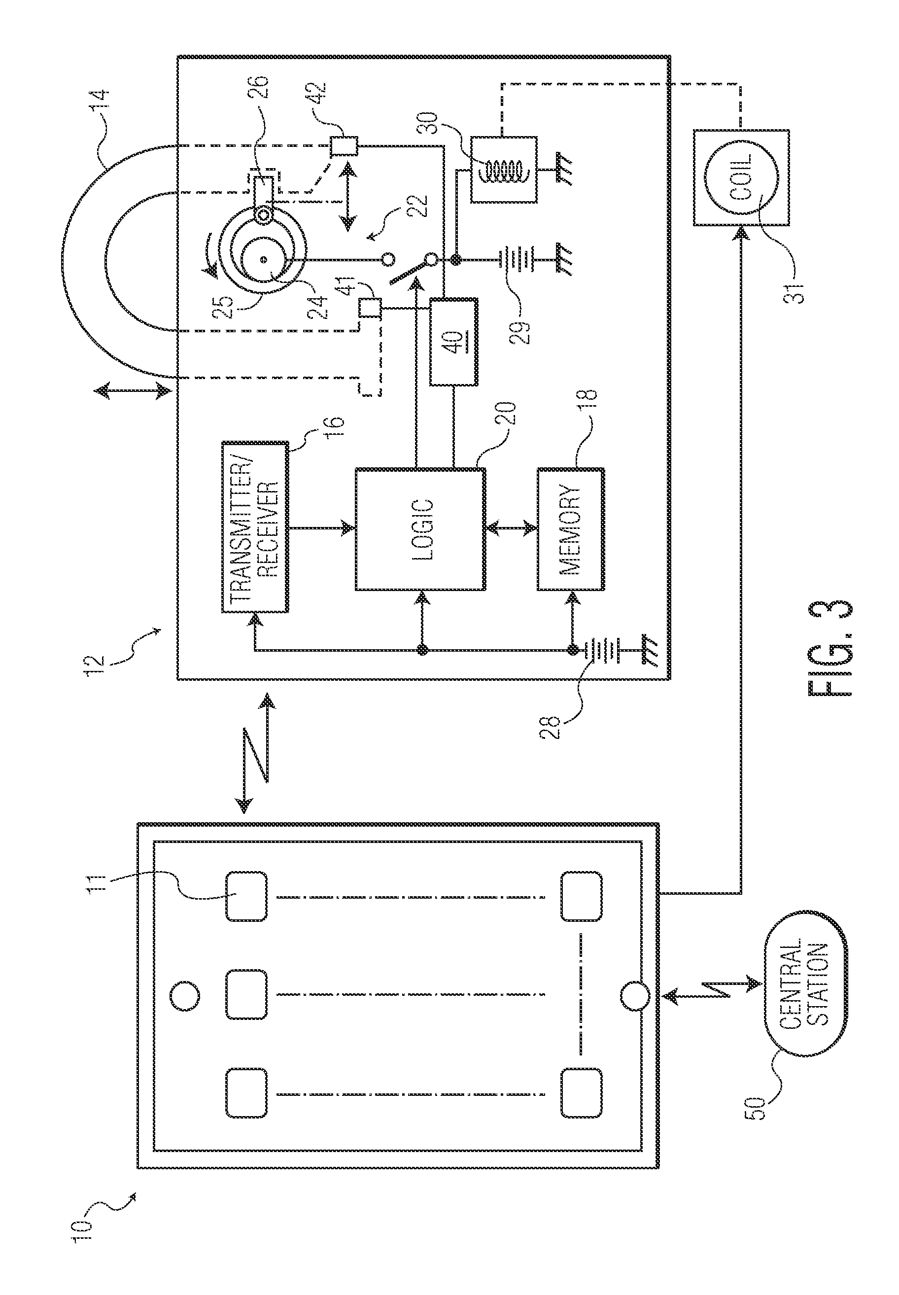
[0070]The preferred embodiments of the present invention will now be described with reference to FIGS. 1-3 of the drawings. Identical elements in the various figures are identified with the same reference numerals.

[0071]Briefly in overview, a trigger-locking device is designed to be manually installed on a gun in the recess behind the trigger in the lower receiver mechanism, blocking rearward movement of the trigger. When installed and locked, the trigger-locking device cannot be unlocked without the use of an “electronic key” which is described below. When a proper electronic signature is transmitted to the trigger-locking device by the electronic key, a movable member within the trigger-locking device is moved to an unlocked position, allowing the device to be opened and manually removed from the gun.

[0072]The trigger-locking device has a Bluetooth receiver for some other type of signal receiver) and a stored number. When this particular number is received from a smartphone or sim...


PUM


Abstract

A gun trigger-locking device which is configured to be manually installed on a gun with a trigger-blocking member disposed behind the trigger to prevent the gun from being fired. The device includes a data receiver, a data memory and a logic device for determining whether data received by the receiver is the same as data stored in the memory. If a data match is indicated, the logic device causes an electromagnetic device to move a locking member to an unlocked position, permitting the trigger-blocking member to be unlocked so the gun can be fired. A separate electronic key is provided to transmit unlock data to the data receiver of the trigger-locking device. This unlock data includes biologic data identifying the gun owner or some other person who is licensed or otherwise authorized to fire the gun. The trigger-locking device includes means for detecting when the device has been tampered with or removed from the gun, and transmitting an alert signal to the electronic key, for relaying to a central station.

Description

CROSS-REFERENCE TO RELATED APPLICATIONS[0001]This application claims priority from U.S. patent application Ser. No. 13 / 763,951 filed Feb. 11, 2013 (now U.S. Pat. No. 8,893,420) and application Ser. No. 14 / 017,666 filed Sep. 4, 2013 (now U.S. Pat. No. 8,919,024) both entitled “SECURE SMARTPHONE-OPERATED GUN TRIGGER LOCK” as well as application Ser. No. 14 / 140,658 filed Dec. 26, 2013 (now U.S. Pat. No. 8,931,195) and its divisional U.S. patent application Ser. No. 14 / 513,344 filed Oct. 14, 2014, and entitled “SECURE SMARTPHONE-OPERATED GUN LOCK WITH MEANS FOR OVERRIDING RELEASE OF THE LOCK.”[0002]This application is a continuation-in-part of the aforesaid application Ser. No. 14 / 513,344.BACKGROUND OF THE INVENTION[0003]The present invention relates to a gun lock for a trigger-operated gun which is designed to be installed on the gun in a position adjacent or behind the trigger to prevent the trigger from firing the gun.[0004]Mechanical gun locks are designed to be installed on the gun...

Claims


Application Information

Patent Timeline
Patent Type & Authority Patents(United States)
IPC IPC(8): F41A17/06
CPCF41A17/063F41A17/066
Inventor MILDE, JR., KARL F.
Owner MILDE JR KARL F
Why Eureka
Try Eureka