

Prosthesis having a large femoral head
- Summary
- Abstract
- Description
- Claims
- Application Information
AI Technical Summary
Benefits of technology
Problems solved by technology
Method used
Image

Examples
Embodiment Construction
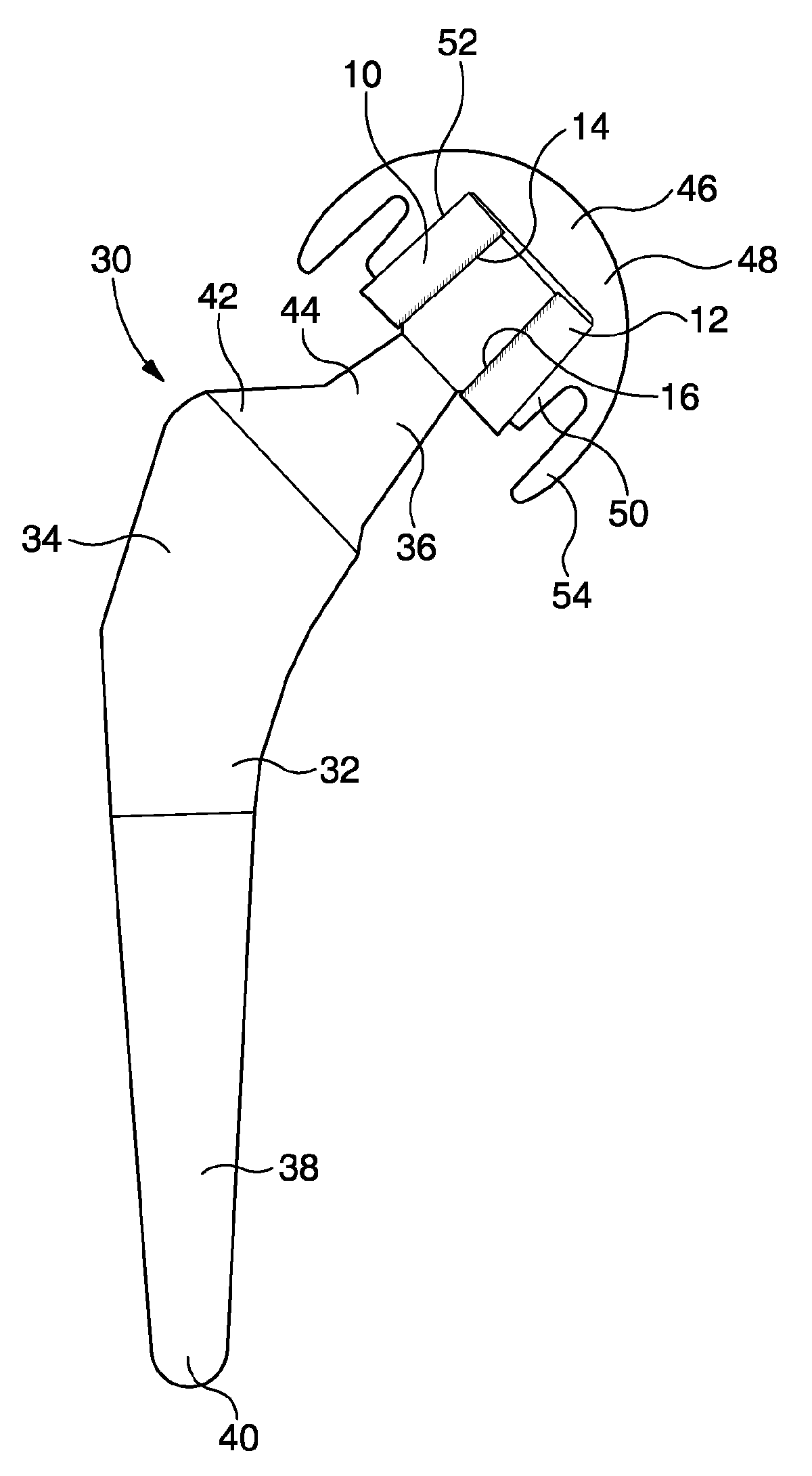
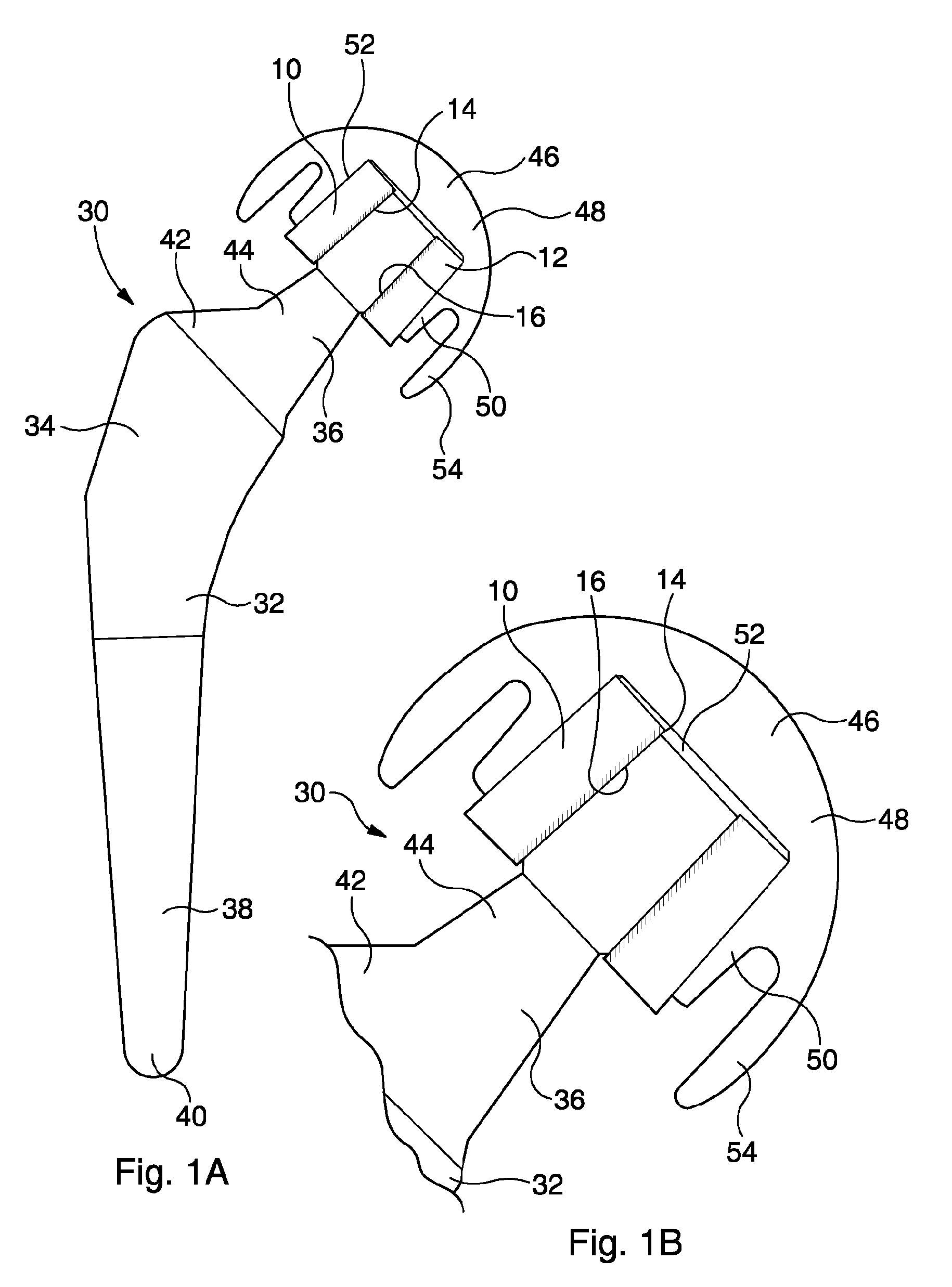
[0052]With reference to FIGS. 1A and 1B, there is illustrated a prosthesis 30 for a THR procedure. The prosthesis 30 comprises a femoral stem 32, a femoral head 46 and a sleeve 10.
[0053]The femoral stem 32 comprises a shoulder 34, a neck 36 and a leg 38. The shoulder 34 has a slightly curved form, tapering inwardly in a distal direction to the most proximal end of the leg 38. The leg 38 comprises a straight elongate conical section tapering inwardly in a distal direction and terminating in a rounded tip 40. The neck 36 extends from the widest and most proximal end of the shoulder 34 and comprises a base 42 and a frustoconical femoral neck portion constituted by a cone 44. The base 42 tapers more in a lateral direction than in a proximal direction, while the cone 44 comprises a frustoconical taper extending in a proximal-lateral direction.
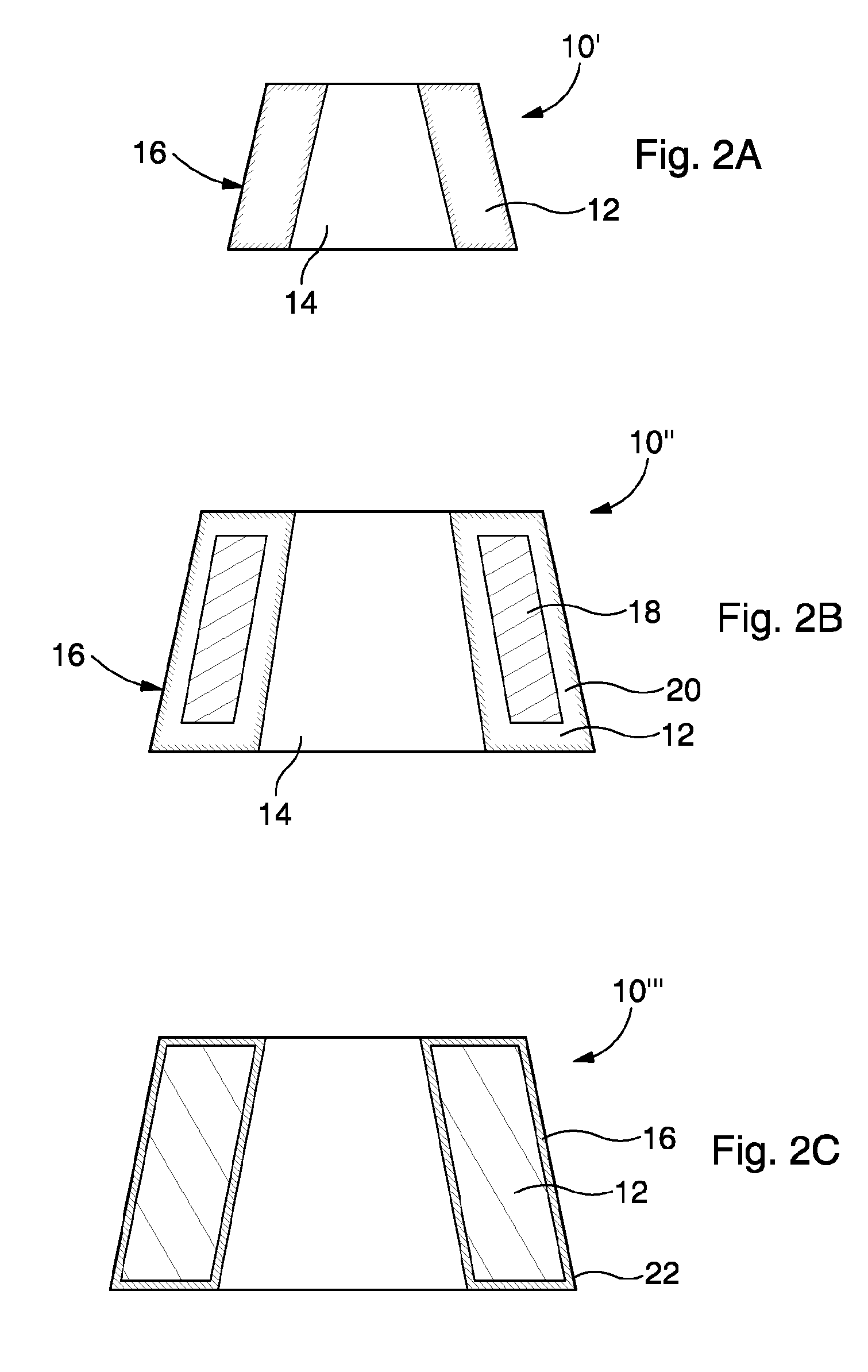
[0054]The sleeve 10 comprises a frustoconical body 12 having a substantially frustoconically tapering internal recess 14. A surface 16 of the reces...
PUM
| Property | Measurement | Unit |
|---|---|---|
| Length | aaaaa | aaaaa |
| Thickness | aaaaa | aaaaa |
| Diameter | aaaaa | aaaaa |
Abstract
Description
Claims
Application Information