

Method of charging a lithium-sulphur cell
a lithium sulphur cell and charging method technology, applied in the direction of secondary cell servicing/maintenance, sustainable manufacturing/processing, final product manufacturing, etc., can solve the problems of affecting the longevity of the cell, unable to charge the cell to the fixed cut-off voltage, so as to reduce the effect of reducing the risk of overcharging the cell and reducing the risk of capacity fad
- Summary
- Abstract
- Description
- Claims
- Application Information
AI Technical Summary
Benefits of technology
Problems solved by technology
Method used
Image

Examples
Embodiment Construction
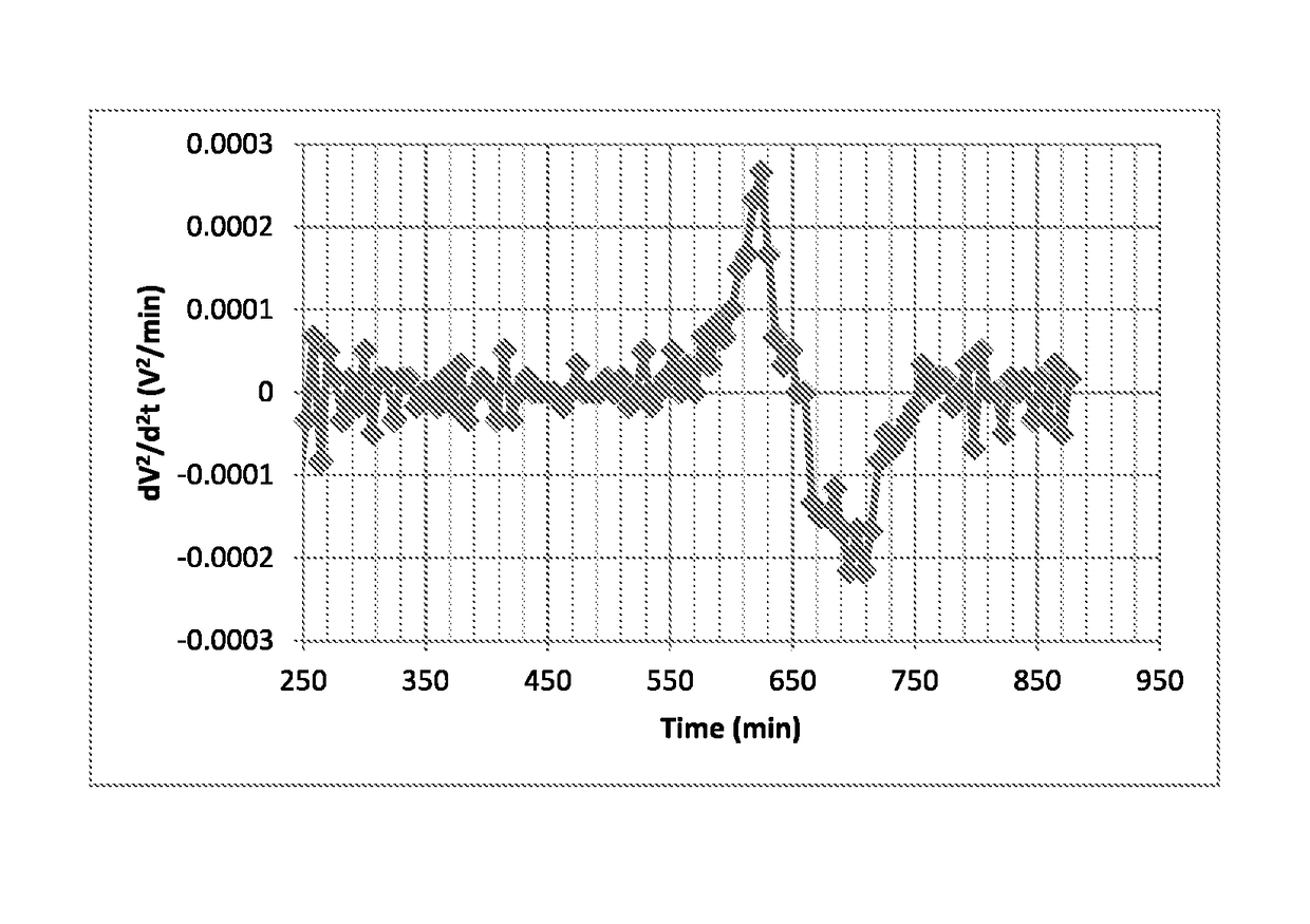
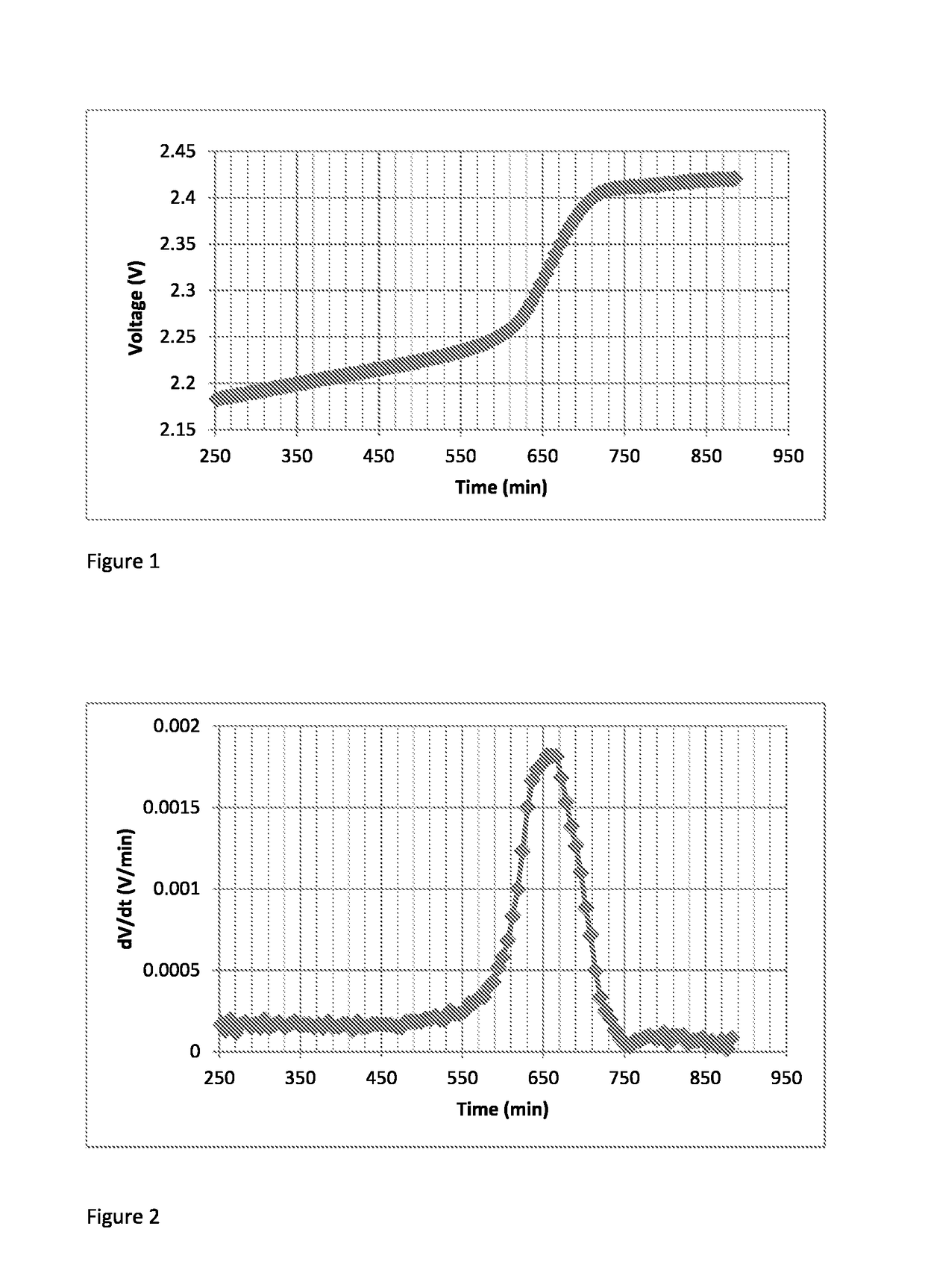
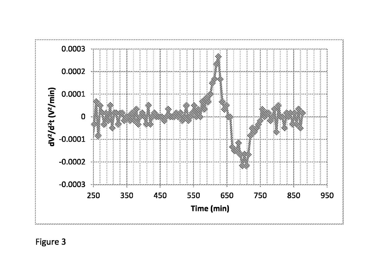
[0043]In this example, the voltage, V, of a cell during charge as a function of time (t) was monitored. The voltage was plotted as a function of time in FIG. 1. As can be seen from FIG. 1, the cell transitions between a first stage of charge to a second stage of charge in the region between about 2.2 V and 2.4 V. In this region, a reference capacity, Qref, of the cell is determined by calculating dV / dt at a range of points. The reference capacity, Qref, is determined at the point at which dV / dt is at a maximum, and, d2V / dt2 is zero (see FIGS. 2 and 3). This is the inflexion point between the first and second stages of discharge. In this Example, charging of the cell was terminated when the capacity reached 1.25Qref. This process may be repeated for each charge cycle of the cell. In this way, the termination voltage will be determined according to the specific characteristics (e.g. charging profile) of the cell at the charge cycle in question. This reduces the risk of over-charging, ...
PUM
| Property | Measurement | Unit |
|---|---|---|
| voltage | aaaaa | aaaaa |
| voltage | aaaaa | aaaaa |
| voltage | aaaaa | aaaaa |
Abstract
Description
Claims
Application Information