Cable carrier chain for leading edge mobile slat for an aircraft wing

a mobile slat and carrier chain technology, applied in the direction of hoisting chains, wing adjustments, hauling chains, etc., can solve the problems of large size along the direction of the wing span and/or along the chord, and the risks of mechanical interference between the different elements present in the forward part of the fixed central body are not negligible, so as to improve the global aerodynamic efficiency of the aircraft, reduce the risk of mechanical interference with the different elements already present in the forward part of the fixed

Active Publication Date: 2013-04-02
SONACA
View PDF8 Cites 3 Cited by
  • Summary
  • Abstract
  • Description
  • Claims
  • Application Information

AI Technical Summary

Benefits of technology

[0019]This reduction in the global size along the direction of the wing span and the wing chord advantageously makes it easy to fit it inside the forward part of the wing fixed central body, although this area is already very congested, particularly due to the presence of the slat movement mechanisms. In this respect, note that the risks of mechanical interference with the different elements already present within the forward part of the fixed central body are advantageously reduced. In particular, the chain kinematics is not at all disturbed by the slat rotary actuation shaft, although it is arranged in the direction of the wing span in the forward part of the wing fixed central body, given that the design of the chain specific to this invention is such that it can move around this actuation shaft, along said above-mentioned spherical surface.
[0020]Note also that the single point towards which the articulation axes converge may be fixed freely on the mobile slat rotation axis, which makes it possible to optimise adaptation of the size to the internal architecture of the wing concerned.
[0021]Furthermore, due to design that is perfectly adapted to the rotary nature of the relative displacement of the mobile slat relative to the fixed central body, the necessary opening on the fixed central body to allow the chain to pass through is very much reduced. This reduction of the opening can increase the global aerodynamic efficiency of the aircraft.
[0027]Preferably, the cables and the chain itself can be protected by a flexible plastic jacket external to the chain that does not disturb its operation. The conferred protection is designed to prevent shocks during maintenance and aggression by chemical agents and fluids used in the aircraft. The first link of the chain can possibly be metallised to provide protection against lightning.

Problems solved by technology

Despite their widespread use, they have several disadvantages, including their large size when extended.
This disadvantage related to the large size along the direction of the wing span and / or along its chord, is particularly problematic when these mechanical structures are housed in a forward part of the wing fixed central body which is already congested, particularly due to the presence of slat movement mechanisms.
Therefore, risks of mechanical interference between the different elements present in the forward part of the fixed central body are not negligible.
Furthermore, the design of these mechanical structures is not well adapted to the rotational nature of the relative displacement of the mobile slat relative to the fixed central body.
This creates another disadvantage which is that a large opening has to be provided on the fixed central body to allow the mechanical structure to pass while it is being extended.
Such an opening reduces the aerodynamic efficiency, and it must be limited or closed by a closer and an aerodynamic seal.
This increases the complexity and significantly complicates the general design of the mechanical system.
Furthermore, the use of known mechanical means connecting the leading edge mobile slat to the fixed central body has a harmful effect on aerodynamic performances.

Method used


Image

  • Cable carrier chain for leading edge mobile slat for an aircraft wing
  • Cable carrier chain for leading edge mobile slat for an aircraft wing
  • Cable carrier chain for leading edge mobile slat for an aircraft wing

Examples


Embodiment Construction

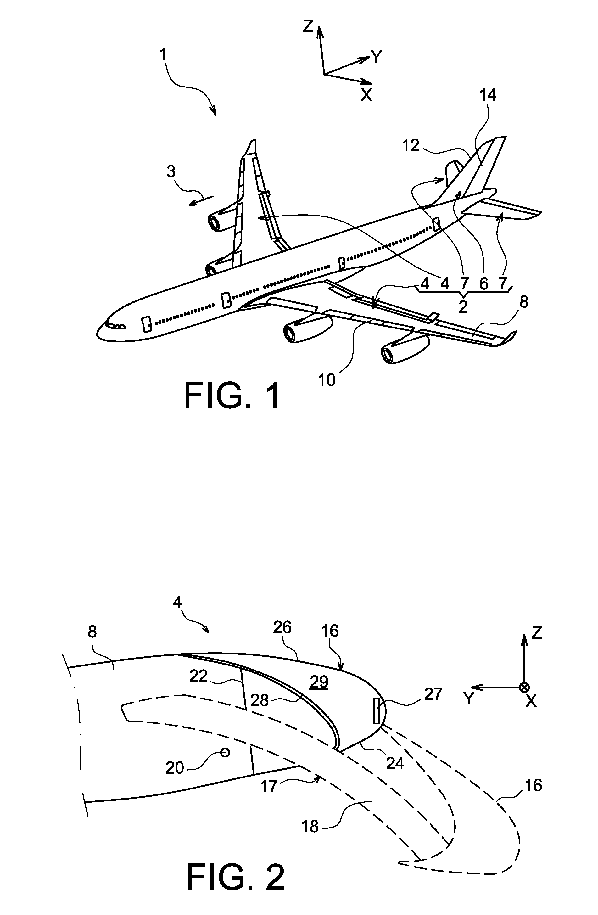
[0042]FIG. 1 shows an aircraft with a wing 2 composed of a plurality of wing elements, also called aerodynamic lift surfaces.

[0043]In the following description, the terms “forward” and “aft” should be considered relative to a direction of progress of the aircraft that occurs as a result of the thrust applied by the aircraft engines, this direction being shown diagrammatically by the arrow 3.

[0044]The wing elements of the aircraft 1 include two principal wings 4, a vertical stabiliser 6 and two horizontal stabilisers 7 at the aft end of this aircraft. Each of the two wings 4 may be fitted with at least one leading edge mobile slat connected to a wing fixed central body through a cable carrier chain according to the invention as will be shown below in a detailed manner for one of these two wings.

[0045]Concerning the wings 4, as mentioned above, each wing comprises a wing fixed central body 8, also called the principal central portion, this body forming practically the entire wing and ...


PUM


Abstract

An aircraft wing comprising a wing fixed central body, and a leading edge mobile slat (16) designed to be moved in rotation relative to the fixed central body along a circular trajectory inscribed on a sphere with center (C). According to the invention, the wing also comprises a cable carrier chain (30) comprising links (34) articulated to each other through articulation axes (44) that converge towards a single point, the chain being connected at its two ends to the fixed central body and to the mobile slat. Furthermore, the single point is the center (C) of the sphere, located on a rotation axis (42) of the leading edge mobile slat relative to the wing fixed body.

Description

TECHNICAL FIELD[0001]This invention generally relates to the domain of means used to support cables fixed on two parts free to move relative to each other along a circular trajectory.[0002]These means that make it possible to support cables are also called cable transfer means or guide means between two parts free to move relative to each other, with a design that allows them to follow the relative displacement between the two parts onto which the cables are connected. For example the cables may be electrical or other cables.[0003]The invention relates more specifically to the domain of aircraft wings, such cable carrier means being provided between a wing fixed central body and a leading edge mobile slat that will be rotated relative to the fixed central body along a circular trajectory that can be inscribed on a sphere. For guidance, the cables supported by the means provided for this purpose are electrical cables that will supply power to an electrical de-icing system integrated ...

Claims


Application Information

Patent Timeline
Patent Type & Authority Patents(United States)
IPC IPC(8): B64C9/24B64C13/30
CPCB64C9/22H02G3/0475F16G13/16B64D15/12
Inventor CREPIN, JEAN-PHILIPPEGODFROID, XAVIERSOUCHON, OLIVIER
Owner SONACA
Why Eureka
Try Eureka