Reusable cable tie

a cable tie and reusable technology, applied in the field of cable tie, can solve the problems of increasing the manufacture cost of cable tie, limited reliability, relative structural and operational complexity of the assembly,

Active Publication Date: 2016-11-10
KIERSTEAD RICHARD MARTIN
View PDF2 Cites 22 Cited by
  • Summary
  • Abstract
  • Description
  • Claims
  • Application Information

AI Technical Summary

Benefits of technology

[0021]In another embodiment of the present invention, the elongated strap is provided laterally, at each side of the multiplicity of teeth and the multiplicity of grooves, starting from their bottoms, with an ascending slanted zone, followed by an externally directed descending slanted zone, and terminating into a straight zone. The flat indented zone includes a short, slightly widened portion preceded by a first retaining portion starting from the internal edge. The first retaining portion, lengthwise, has such a size that enables the buckle to be lodged there, when the reusable cable tie is in a final closed position. A second retaining portion succeeds the short, slightly widened portion extending up to the external edge. The second retainin

Problems solved by technology

The main disadvantages of the foregoing cable tie reside in the fact that its components are structurally complicated and, consequently, their manufacture costs are increased and their reliability is limited.
Among the main disad

Method used


Image

  • Reusable cable tie
  • Reusable cable tie
  • Reusable cable tie

Examples


Embodiment Construction

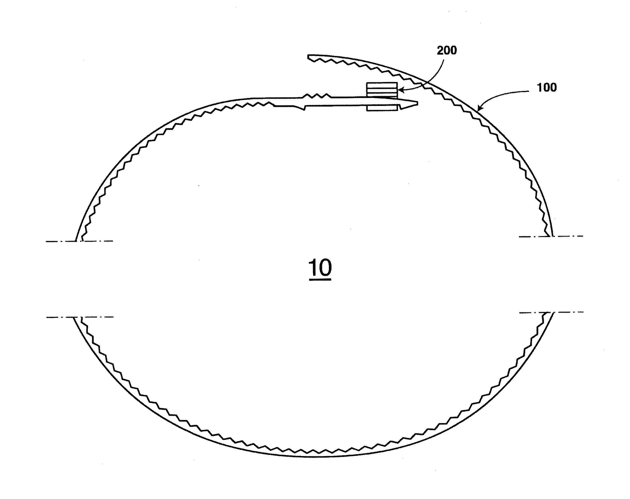
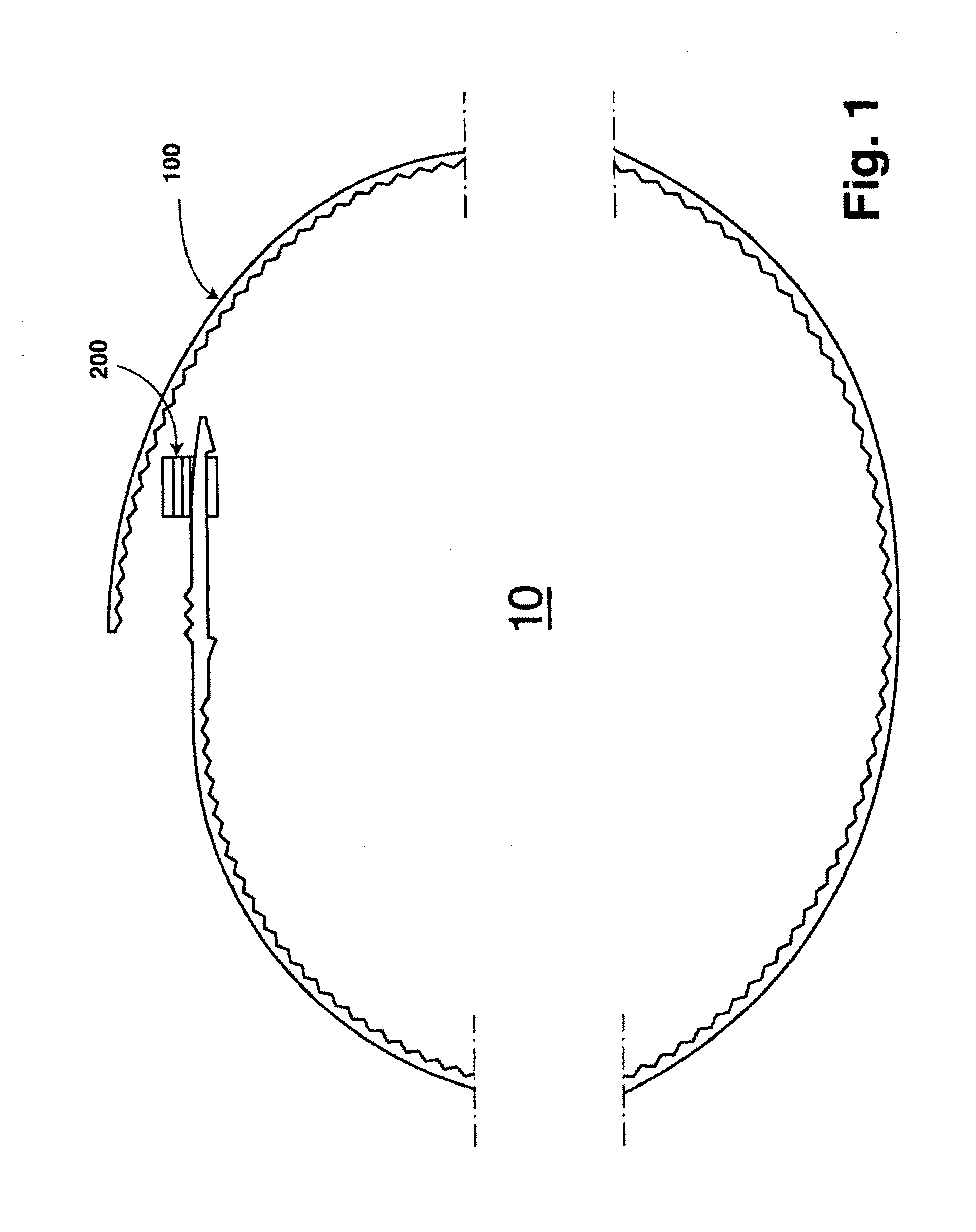
[0032]The accompanying drawings, as above described, illustrate a preferred embodiment of a “Reusable cable tie”. This preferred embodiment is generally designed with numeral 10. Referring to FIGS. 1 to 9, in which like numerals indicate like elements, the reusable cable tie, already referenced as 10, includes an elongated strap 100, made of semi-rigid plastic material, and a buckle 200, made of rigid plastic material and used for interlocking with elongated strap 100.

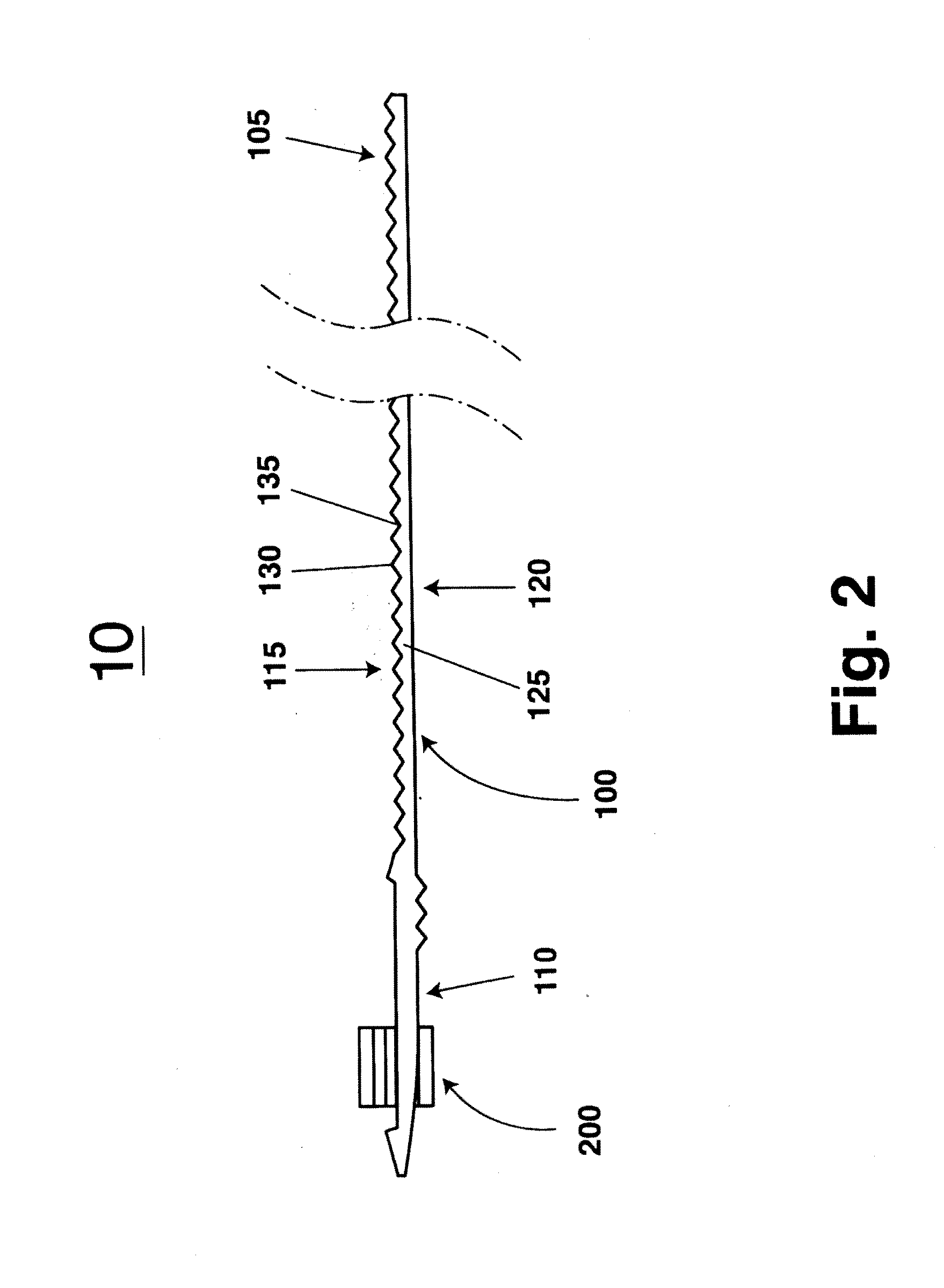
[0033]Elongated strap 100 comprises a first end 105 and a second end 110, an inner side 115 and an outer side 120. Elongated strap 100 further comprises a rack 125 having a multiplicity of teeth 130, equally spaced and transversely located with respect to the direction of elongated strap 100. Each tooth of multiplicity of teeth 130 has in cross-section a triangular shape.

[0034]Multiplicity of teeth 130 alternates with a multiplicity of grooves 135. Each groove of multiplicity of grooves 135 has a shape and a size comme...


PUM


Abstract

A reusable cable tie comprises an elongated strap, made of semi-rigid plastic material, and a buckle, made of rigid plastic material, for interlocking with the elongated strap. The elongated strap includes a first end a second end, an inner side and an outer side. The inner side incorporates a rack with a multiplicity of teeth, alternating with a multiplicity of grooves. The multiplicity of teeth extends from the first end up to a flat indented zone adjoining the second end that is provided with several teeth and grooves, the several teeth projecting from the outer side in an external zone corresponding to a beginning of the flat indented zone. The buckle incorporates a cavity so shaped and sized as to allow a passage through of the first and the second end of the elongated strap.

Description

I. BACKGROUND OF THE INVENTION[0001]1. Field of the Invention[0002]The present invention relates, in general, to cable ties and, in particular, to a reusable cable tie.[0003]2. Description of the Prior Art[0004]Cable ties are widely used for wrapping their straps around objects, then tightening them and, finally, securing them. The known cable ties, once secured around objects, cannot be turn loose or reused. The remove them, the only solution is to use cutting means.[0005]Several attempts to remediate the foregoing situation have been made. For example, U.S. Pat. No. 8,516,660, dated Aug. 27, 2013 and granted to Ku for a “Cable Tie”. This patent discloses a cable tie including a slot base with an insertion hole, a belt and at least one fastener. At least one surface of the insertion hole is slanted. A plurality of locking teeth is arranged at a surface on one side of the belt. The fastener is mounted into the insertion hole of the slot base correspondingly. The fastener includes a ...

Claims


Application Information

Patent Timeline
IPC IPC(8): B65D63/10
CPCB65D63/1027B65D2563/103B65D2563/107F16B2/08H02G3/30Y02W30/80Y10T24/141Y10T24/1498F16L3/2336
Inventor KIERSTEAD, RICHARD MARTIN
Owner KIERSTEAD RICHARD MARTIN
Why Eureka
Try Eureka