
Device comprising a guide, rail system and transport mechanism for use in such a device

a technology of rail system and transport mechanism, which is applied in the direction of wing accessories, curtain suspension devices, manufacturing tools, etc., can solve the problems of limited load-bearing capacity of carriers, inability to support wheels running thereon, and interrupted running surfaces of rails, etc., to achieve easy and manoeuvrable manner, light construction, and reliable device

Inactive Publication Date: 2012-09-04
ESPERO
View PDF6 Cites 7 Cited by
  • Summary
  • Abstract
  • Description
  • Claims
  • Application Information

AI Technical Summary

Benefits of technology

[0010]It is therefore an object of the invention to provide a reliable device for displacing relatively heavy objects, such as, for example, wall panels with a height of 5-13 m, along different tracks along a rail system, these objects being able to be displaced along branches and crossings of the rail system, in the desired direction, in an easy and manoeuvrable manner. It is additionally an object of the invention to provide a relatively lightly constructed rail system with which heavy objects can be accurately and easily displaced with low expenditure of force.
[0013]The load which can be displaced with the device may comprise any load, such as an object which is moved through a room, such as in the assembly or manufacture of a product, a foodstuff, or some other object. The load may be formed by a wall panel having a relatively large dimension, such as a height of between 5 m and higher, for example 13-20 m. These panels can be guided manually by the user along the tracks to a desired position, such as a functional position, which divides a room into parts, and a parking position, in which the panels are placed flat one against the other. Through the use of the carrier according to an embodiment, the runners of the panels, close to a branch or crossing, are supported such that the panels can be quickly and easily manipulated along the branch or crossing with just slight application of force, so that the panels can be brought easily into position even by less strong members of staff The rails and especially the running surfaces can be lightly constructed, so that a wall system is obtained which can be easily transported and assembled and which is relatively cheap.
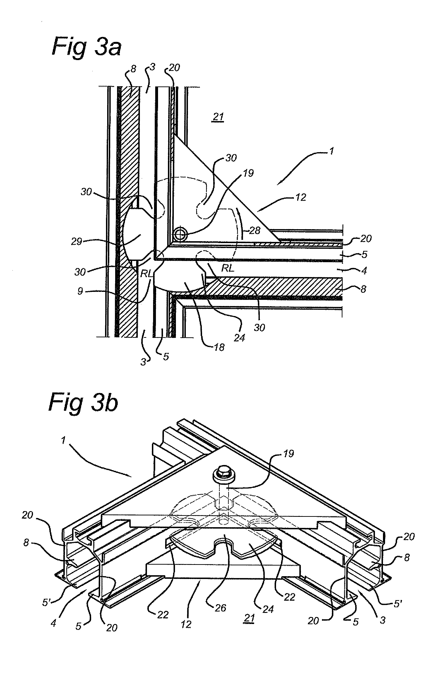
[0014]In one embodiment, the transport mechanism comprises a supporting body which is pivotable. The pivotable construction of the transport mechanism ensures a simple movement of the supporting body in its movement from the take-up position into the delivery position. The transport mechanism can hence be made relatively simply and cheaply. In an embodiment, the rotation axle extends perpendicular to the running surfaces. This construction ensures that the play of forces upon the transport mechanism during the movement from the take-up position to the delivery position remains relatively equal. This simplifies the required construction of the transport mechanism. The supporting body may be pivotable around a pivot axis. The pivot axis may be, in an embodiment, positioned with an offset with respect to the centre of the crossing or junction.
[0015]In one embodiment, the running surfaces are fastened to side walls situated transversely to the running surfaces, the carrier being situated between the side walls and the pivot axle being mounted close to the crossing or junction along an outer side of the side walls. The side walls, close to the pivot axle, may have a slot through which the transport mechanism reaches to between the side walls. The mounting of the pivot axle on the outer side of the side walls and the provision of a slot in the side walls of the rails ensures that existing rail systems can be adapted and can be provided with a transport mechanism by retrofitting. On the outer side of the side walls there is additionally enough place for the mounting of the transport mechanism. The transport mechanism can hence be made sufficiently strong. The placement of the pivot axle at a distance from the running surfaces, in combination with a transport mechanism reaching to between the running surfaces, also ensures that an accurate transfer of the carrier from a first track to a second track is possible.
[0018]In one embodiment, at least one running surface of each track is realized as a first running surface, the device further comprising a second running surface situated at a transverse distance above the first, and the carrier comprising two bevelled wheels situated at a transverse distance apart, which are rotatable about a wheel axle situated transversely to the running surfaces, which wheels engage with their bevel with respective running surfaces situated at a transverse distance apart. This embodiment has the advantage that the transport mechanism can easily engage with the wheel supported by a running surface. The wheel axle situated transversely to the running surfaces makes it possible to easily engage the carrier. This simplifies the transport from the first track to the second track in case of a change of direction.
[0020]In an embodiment, the first and second pair of running surfaces intersect at equal height. The carrier can hence be transferred at a same height. Accordingly, there are no height differences which need to be bridged. This simplifies the construction and guarantees a minimal expenditure of force by a user in the displacement of a panel and the transfer of the carrying device from a first track to a second track.

Problems solved by technology

A drawback of the known device lies in the fact that at crossings, at least one of the running surfaces of the rails is interrupted and the wheel running thereon is not supported.
This makes the load-bearing capacity of the carrier limited, since the bearing load is defined by a single wheel.
In addition, as a result of lack of support at a crossing or junction, the carrier will run somewhat out of the vertical.
In addition, it is not possible to carry out the displacement rapidly and with low force application by hand.

Method used


Image

  • Device comprising a guide, rail system and transport mechanism for use in such a device
  • Device comprising a guide, rail system and transport mechanism for use in such a device
  • Device comprising a guide, rail system and transport mechanism for use in such a device

Examples


Embodiment Construction

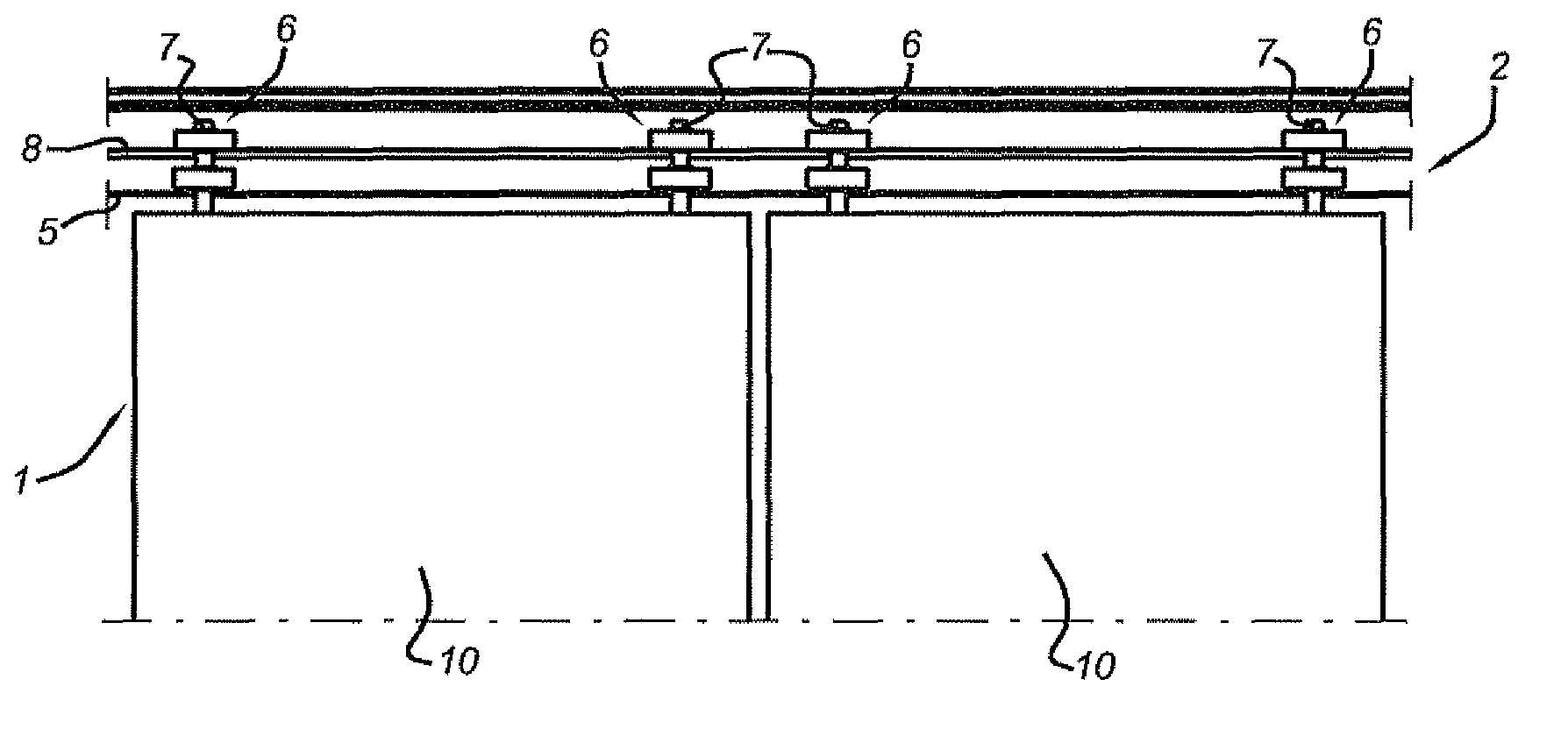
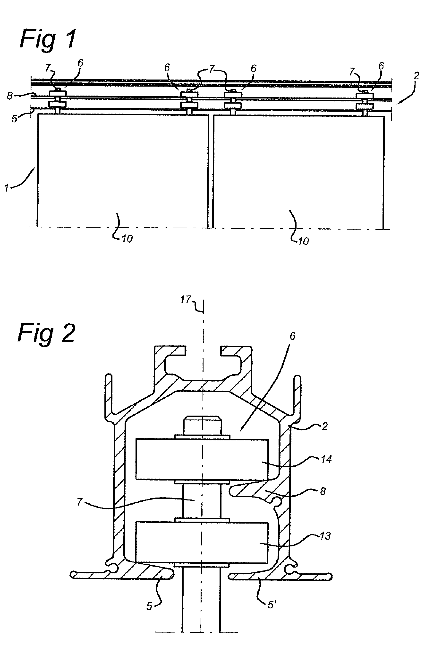
[0027]FIG. 1 shows a known device 1 for displaceably suspended panels 10 according to the prior art. The device 1 comprises a guide 2 having substantially parallel running surfaces 5, 8. The device 1 comprises carriers 6 suspended displaceably over the running surfaces 5, 8. The carrier 6 has a bearing axle 7, extending transversely to the running surfaces 5, for fastening of a load 10, such as, for example, a wall panel. The bearing axle 7 extends between the running surfaces 5, 8, as shown in FIG. 2.

[0028]FIG. 2 shows a detail of a cross section of a carrier 6 in a guide 2 of a device 1 for displaceably suspended panels 10 according to the prior art. The carrier 6 comprises a bearing axle 7, which reaches to between the running surfaces 5, 8. The carrier may have two bevelled wheels 13, 14, which are situated at a transverse distance apart and are rotatable about a wheel axle 17 situated transversely to the running surfaces 5, 8. The wheels engage with their bevel with respective ...


PUM


Abstract

A device comprising a guide having a first pair of substantially parallel running surfaces, which are placed along a first track at a lateral distance apart, and a second pair of substantially parallel running surfaces, which are placed along a second track at a lateral distance apart. The second pair of running surfaces extends, at a crossing or junction, transversely to the first pair of running surfaces. A carrier is displaceable over at least the running surfaces and has a bearing axle, extending transversely to the running surfaces, for fastening of a load, which bearing axle extends between the running surfaces. The device, close to the crossing / junction, has a transport mechanism. The transport mechanism is movable between a take-up position in the first track, for load-bearing engagement with the carrier, and a delivery position in the second track, for release of the carrier. The invention further relates to a rail system and a transport mechanism.

Description

BACKGROUND OF THE INVENTION[0001]1. Field of the Invention[0002]The application relates to a device comprising a guide having a first pair of substantially parallel running surfaces, which are placed along a first track at a lateral distance apart, and a second pair of substantially parallel running surfaces, which are placed along a second track at a lateral distance apart, which second pair, at a crossing or junction, extends transversely to the first pair of running surfaces, and further comprising at least one carrier displaceable over the running surfaces, which carrier has a bearing axle, extending transversely to the running surfaces, for fastening of a load, which bearing axle extends between the running surfaces.[0003]The application also relates to a rail system and a transport mechanism for use in such a device.[0004]2. Description of Related Art[0005]A device of the abovementioned sort, for the displacement of mobile wall panels along a rail system mounted on the ceiling...

Claims


Application Information

Patent Timeline
IPC IPC(8): B61D19/00
CPCE05D15/0613E05Y2201/692E05Y2800/21Y10T16/376E05Y2800/268E05Y2201/612Y10T16/35E05Y2900/142
Inventor BANKS, ADRIANKAANDORP, RUUD
Owner ESPERO
Learn More