Unlock instant, AI-driven research and patent intelligence for your innovation.

Position detection device

Inactive Publication Date: 2016-12-15
PANASONIC INTELLECTUAL PROPERTY MANAGEMENT CO LTD
View PDF1 Cites 7 Cited by
  • Summary
  • Abstract
  • Description
  • Claims
  • Application Information

AI Technical Summary

Benefits of technology

The present invention aims to provide a position detection device that can minimize the likelihood of there being drive periods for excitation coils that overlap during the activation of detectors.

Problems solved by technology

However, the conventional example described above does not consider a circumstance in which drive periods of the excitation coils overlap each other on activation of the detectors.
Therefore, in the conventional example described above, when the drive periods of the excitation coils overlap each other on activation of the detectors, for example, detection processes by the detectors may be simultaneously performed, which may lead to mutual magnetic interference.

Method used


Image

  • Position detection device
  • Position detection device
  • Position detection device

Examples


first embodiment

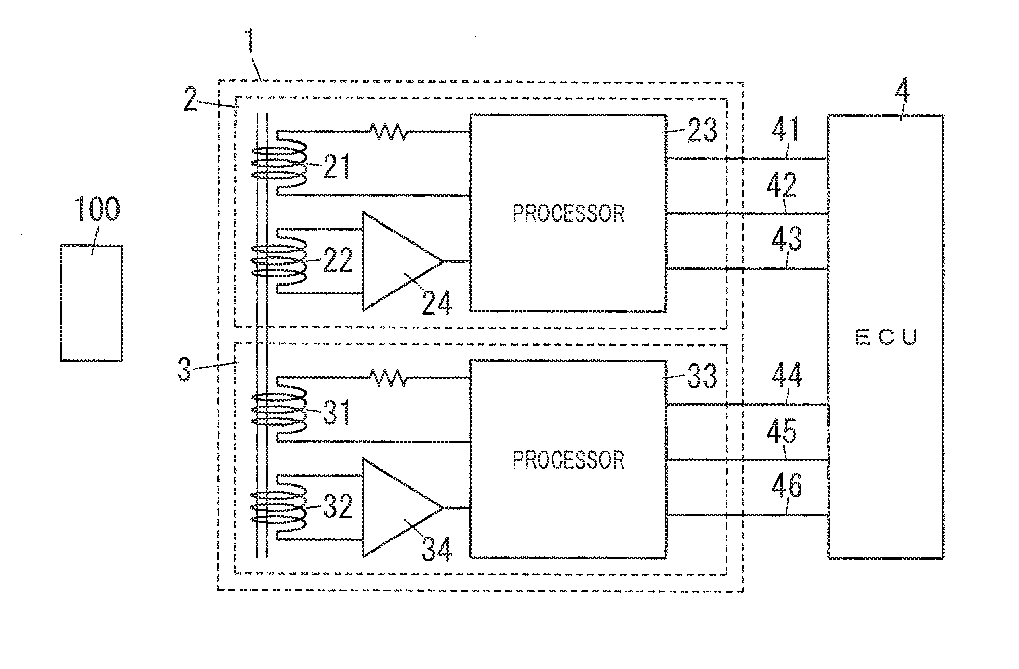
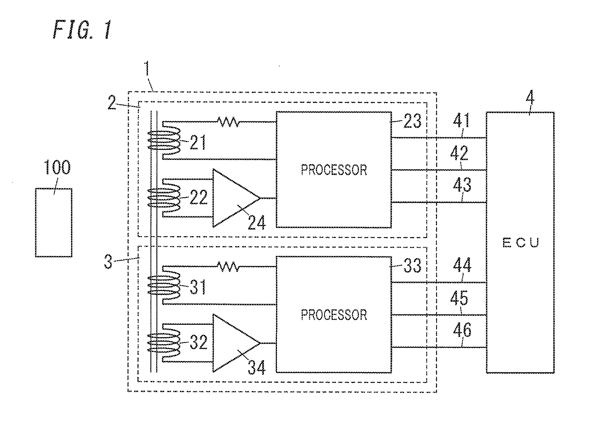
[0025]As illustrated in FIG. 1, a position detection device according to a first embodiment of the present invention includes a detector 2 (here, first detector) and a detector 3 (here, second detector). The detector 2 includes a (first) excitation coil 21, a (first) detection coil 22, and a (first) processor 23. The detector 3 includes a (second) excitation coil 31, a (second) detection coil 32, and a (second) processor 33. The excitation coil 21 is magnetically coupled to the detection coil 22 and the detection coil 32. The excitation coil 31 is magnetically coupled to the detection coil 22 and the detection coil 32.

[0026]The processor 23 is configured to intermittently execute a (first) acquisition process during a measurement period of the processor 23. The (first) acquisition process is a process of driving the excitation coil 21 and acquiring a (first) detection signal Y1 (see FIG. 2) induced in the detection coil 22 depending on the position of an object 100 by the driving th...

second embodiment

[0111]While in the position detection device 1 of the first embodiment, the processor 23 (processor 33) monitors whether or not the detection signal Y4 (detection signal Y3) is induced in the detection coil 22 (detection coil 32) during the monitoring period, other configurations may be possible. A position detection device 1 according to a second embodiment of the present invention will be described below with reference to the drawings. The description of elements of the position detection device 1 of the present embodiment which are shown in the position detection device 1 of the first embodiment is accordingly omitted.

[0112]As illustrated in FIG. 12, the position detection device 1 of the present embodiment includes a (first) processor 23 and a (second) processor 33 which are electrically connected to each other via one communication line 5. The (first) processor 23 and the (second) processor 33 can perform bidirectional communication via the one communication line 5.

[0113]Specif...

third embodiment

[0121]A position detection device 1 according to a third embodiment of the present invention will be described below with reference to the drawings. The description of elements of the position detection device 1 of the present embodiment which are shown in the position detection device 1 of the first embodiment is accordingly omitted.

[0122]

[0123]It is possible, although very rare, that due to, for example, a temporal abnormality of a processor 23 (processor 33), a time period during which the processor 23 executes the acquisition process and a time period during which the processor 33 executes the acquisition process partly overlap each other. The time period during which the processor 23 (processor 33) executes the acquisition process is hereinafter referred to as an “execution time period DP1.” That is, as an example illustrated in FIG. 15A, an event occurs in which the execution time period DP1 of the processor 23 and the execution time period DP1 of the processor 33 partly overl...


PUM


Abstract

A processor of a position detection device intermittently performs an acquisition process during a measurement period to acquire a detection signal induced in a detection coil depending on the position of an object by driving an excitation coil. The processor configured to monitor whether or not the processor is executing the acquisition process without driving the excitation coil during a monitoring period set before the measurement period of the processor, and the processor is configured to execute a predetermined process when the processor is executing the acquisition process.

Description

TECHNICAL FIELD[0001]The present invention generally relates to position detection devices, and specifically relates to a position detection device including a plurality of detectors.BACKGROUND ART[0002]An electromagnetic induction-type displacement sensor (position detection device) has been provided which includes two detection circuits (detectors) so that even when a fault occurs on one of the detectors, displacement of an object is detectable by the other of the detectors. Such a position detection device has been disclosed in, for example, Document 1 (JP 2005-265463 A). The position detection device includes two detectors each including a coil drive unit, two drive coils (excitation coils) each connected to the coil drive unit, and two detection coils each connected to the detector. The position detection device further includes an electromagnetic coupling member displaceable relatively to the excitation coils and the detection coils. The coil drive units include oscillation ci...

Claims


Application Information

Patent Timeline
IPC IPC(8): G01D5/22G01B7/00
CPCG01B7/003G01D5/22G01D3/08G01D5/2053
Inventor NIWA, MASAHISAOKADA, KUNITAKAHARAGUCHI, KAZUMA
Owner PANASONIC INTELLECTUAL PROPERTY MANAGEMENT CO LTD